118
SD242
A/Q base
differentiation
Base type
differentiation
0: QA**B is
installed
(A mode)
1: Q**B is
installed
(Q mode)
S
(Initial)
New
Qn(H)
QnPH
QnPRH
Rem
Installed Q
base
presence/
absence
Base type
differentiation
0: Base not
installed
1: Q**B is
installed
Q00J/
Q00/Q01
Installed Q
base
presence/
absence
Base type
differentiation
0: Base not
installed
1: Q**B is
installed
QnU
SD243
No. of base
slots
No. of base
slots
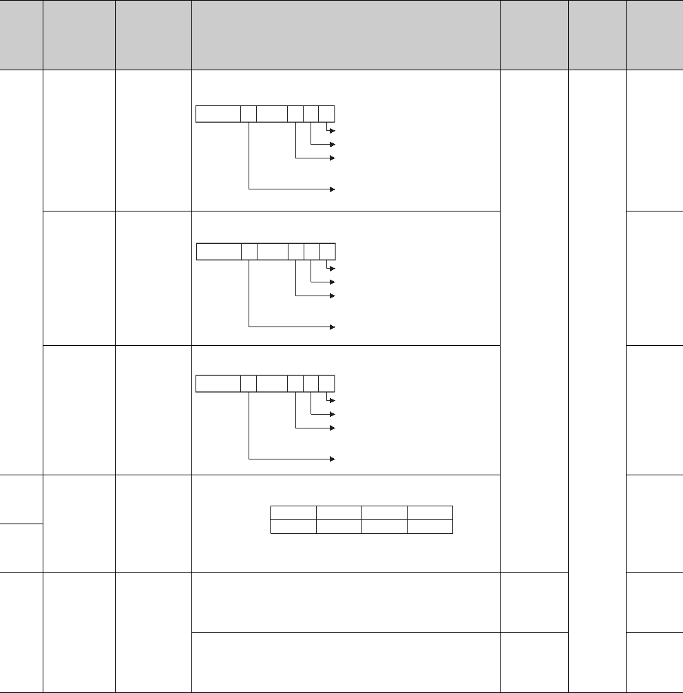
The number of slots used is stored in the area corresponding to each
base unit as shown above.
Qn(H)
QnPH
QnPRH
QnU
Rem
SD244
SD250
Loaded
maximum I/O
Loaded
maximum I/O
No.
When SM250 is turned on, the first two digits of the number, which are
the last I/O number of the mounted modules plus 1, are stored in
binary format.
S
(Request
END)
Qn(H)
QnPH
QnPRH
Rem
The first two digits of the number, which are the last I/O number of the
mounted modules plus 1, are stored in binary format.
S
(Initial)
Q00J/
Q00/Q01
QnU
Rem
No. Name Meaning Explanation
Set by
(When Set)
Corres-
ponding
ACPU
D9
Corres-
ponding
CPU
B7
to
Main base unit
Fixed to 0
B2 B1 B0
Fixed to 0 when an
extension base unit
is not mounted.
to
1st extension base unit
2nd extension base unit
7th extension base unit
B0B1B2B4
to
Fixed to 0
Main base unit
to
1st extension base unit
2nd extension base unit
4th extension base unit
B7
to
Main base unit
Fixed to 0
B2 B1 B0
Fixed to 0 when an
extension base unit
is not mounted.
to
1st extension base unit
2nd extension base unit
7th extension base unit
SD243 Extension 2 Extension 1 Main
Extension 7 Extension 6 Extension 5 Extension 4
Extension 3
B15 B12 B11 B8 B7 B4 B3 B0
SD244


