


4
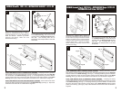
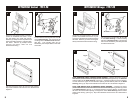
Disconnect the negative battery terminal to
prevent an accidental short circuit. Unclip
the radio trim bezel (the factory pocket will
be attached). Remove (4) screws securing
the factory head unit and disconnect the
wiring.
1 2
Cut and remove all mounting tabs on the
Radio Housing EXCEPT tabs "B". The
mounting tabs can be identified by the
stamped letter on the back of each tab.
EAGLE Talon / MITSUBISHI Eclipse
PLYMOUTH Laser 1990-94
"B"
"B"
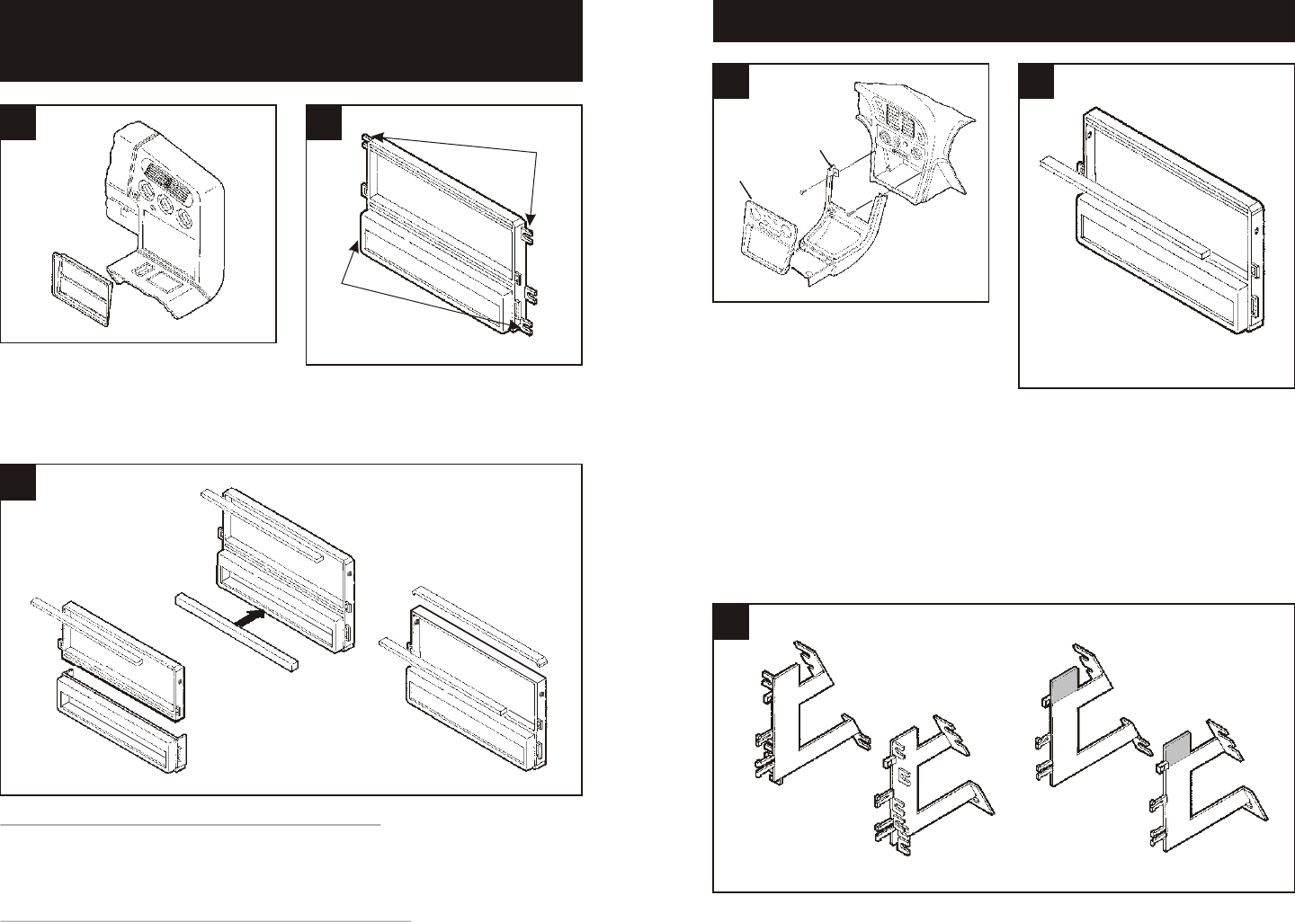
3
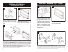
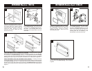
DASH TRIM BEZELS WITH A DIVIDED RADIO OPENING: If keeping the factory pocket is
NOT desired, cut and remove the upper rib from the radio openingand snap the Filler Bar
onto the bottom of the Radio Housing. (see Fig. A). If keeping the factory pocket is desired,
cut and remove the upper rib from the radio opening and the bottom portion of the Radio
Housing. (see Fig. B). Skip to the Installation Instructions for ALL VEHICLES on Page #12.
DASH TRIM BEZELS WITH AN UNDIVIDED RADIO OPENING: Cut and remove the lower
rib from the radio opening and the top portion of the Radio Housing. (see Fig. C). Skip to the
Installation Instructions for ALL VEHICLES on Page #12.
Fig. A
Fig. B
Fig. C
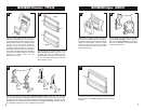
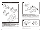
5
Disconnect the negative battery terminal to
prevent an accidental short circuit. Slide the
front seats forward and remove (1) cover
cap and (1) Phillips screw from each side of
the center console. Unsnap the
cupholder/ashtray assembly and remove (2)
Phillips screws exposed. Unclip the radio
trim bezel and remove (2) Phillips screws
exposed. Unscrew the shifter knob.
Disconnect the cigarette lighter and light
wiring. Lift up on the center console and
remove. Remove (4) Phillips screws
securing the factory head unit and
disconnect the wiring.
1
EAGLE Talon / MITSUBISHI Eclipse 1995-98
Center
console
Radio
trim
bezel
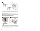
3
Cut and remove mounting tabs "A" and "B"
on the Radio Housing. Cut and remove the
lower rib from the radio opening.
Cut and remove all mounting tabs on Bracket Set #2 EXCEPT tabs "G". The mounting tabs
can be identified by the stamped letter on the back of each tab. (see Fig. A). Once the
mounting tabs are removed, cut and remove the SHADED portions of the Brackets. (see Fig.
B). Skip to the Installation Instructions for ALL VEHICLES on Page #12.
2
"G"
"G"
"G"
"G"
Fig. A
Fig. B