


10 11
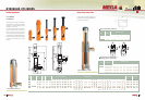
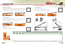
Coupling applications
CC
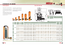
CT Series
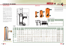
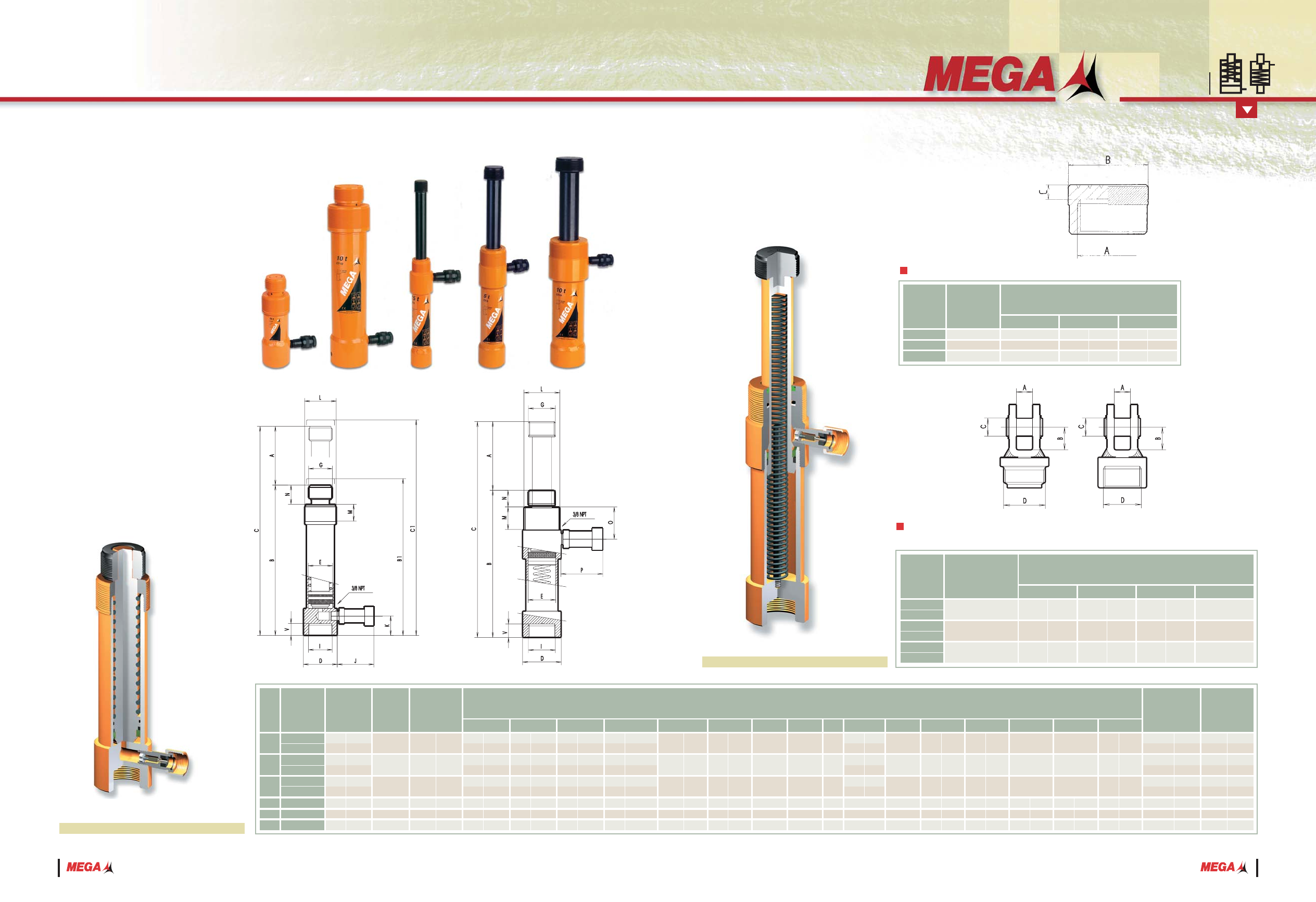
HYDRAULIC CYLINDERS
CC: PUSHING
CT: PULLING
Working pressure: 700 kg/cm
2
/10.000 psi.
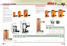
All pistons have an induction hardening
treatment or a salt bath nitriding process
depending on the model.
Each ram is equipped with a female quick
coupler with air dust cap, ref. A-5507-H.
With mounting holes and protected
threaded areas against possible blows for
easy coupling or special tooling applications.
Unlike the pushing cylinders, the pulling
rams retract toward the base to apply
pressure.
These pushing and pulling cylinders can
be original components of the Maintenance
Kits described on page 35.
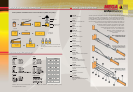
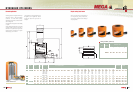
Cross section view ( CC )
CC-5 SERIES
CC-10 SERIES
CC-20 SERIES
A-5142
A-5042
A-5242
Ref. Used with
ABC
Dimensions mm/in.
1
17
/64
2
7
/8
2
29
/32
8
10
12
5
/16
25
/64
15
/32
M26 x 2
M42 x 2,5
M60 x 2,5
32
54
74
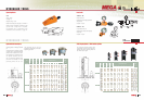
Grooved saddle ( optional )
CC-5A
CC-5B
CC-10A
CC-10B
CC-20A
CC-20B
CT-2,5
CT-5
CT-10
5
10
20
2,5
5
10
Rated
capacity
Ref.
Maximum
capacity
Effective area
tn kN cm
2
in
2
BB1 CC1 DEGI
J
KNOPV
cm
3
in
3
Kg.
Oil volume WeightDimensions mm/in.
LM
lbs.
40
92
73
196
141
368
54
103
199
2,44
5,61
4,45
11,96
8,6
22,46
3,29
6,28
12,14
3
4,9
5,3
9,6
12,1
2,2
5
8,6
17,6
M26 x 2
M42 x 2,5
M60 x 2,5
M26 x 2
M42 x 2,5
M60 x 2,5
70
2
3
/4
70
2
3
/4
70
2
3
/4
----
----
----
1,35
2,2
2,4
4,35
5,5
10
2,25
3,9
8
50
115
50
135
50
130
127
138
138
2
4
1
/2
2
5
5
/16
2
5
1
/8
5
5
7
/16
5
7
/16
55
99,6
194
29,1
51,1
99
8,04
14,52
28,27
4,24
7,45
14,41
1,24
2,25
4,38
0,65
1,15
2,23
177
284
191
332
216
364
270
311
318
6
15
/16
11
3
/16
7
1
/2
13
1
/16
8
1
/2
14
5
/16
10
5
/8
12
1
/4
12
1
/2
184
292
201
342
228
376
----
----
----
7
5
/16
11
1
/2
7
15
/16
13
7
/16
9
14
13
/16
----
----
----
227
399
241
467
266
494
397
449
456
8
15
/16
15
11
/16
9
1
/2
18
3
/8
10
1
/2
19
7
/16
15
5
/8
17
11
/16
17
15
/16
235
407
251
477
278
506
---
---
---
9
1
/4
16
9
7
/8
18
3
/4
10
15
/16
19
15
/16
---
---
---
Stroke
A
mm. in.
M26 x 2
M42 x 2,5
M60 x 2,5
M26 x 2
M42 x 2,5
M60 x 2,5
45
60
79
45
60
79
M38 x 1,5
M56 x 2
M84 x 2
M38 x 1,5
M56 x 2
M84 x 2
----
----
----
70
70
70
2
3
/4
2
3
/4
2
3
/4
----
----
----
70
70
70
2
3
/4
2
3
/4
2
3
/4
----
----
----
33
30
38
35
44
40
1
5
/
16
1
3
/
16
1
1
/
2
1
3
/
8
1
3
/
4
1
9
/
16
B1, C1 with tilting saddle
1
49
/64
2
11
/32
3
1
/8
1
49
/64
2
11
/32
3
1
/8
32
43
60
32
43
60
1
1
/4
1
11
/16
2
11
/32
1
1
/4
1
11
/16
2
3
/8
22
36
48
24
35
35
7
/8
1
7
/16
1
7
/8
15
/16
1
3
/8
1
3
/8
20
26
30
21
24
27
13
/16
1
1
/32
1
3
/16
1
13
/16
15
/16
1
1
/16
18
21
23
16
21
21
11
/16
13
/16
7
/8
5
/8
13
/16
13
/16
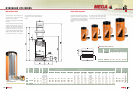
Cross section view ( CT )
CC-5, CT-2,5 SERIES
CC-10, CT-5 SERIES
CC-20, CT-10 SERIES
A-5188
A-5189
A-5088
A-5089
A-5288
A-5289
Ref. Used with
ABC
Dimensions mm/in.
1
1
1
3
/16
20
20
20
25
/32
25
/32
25
/32
18
18
18
23
/32
23
/32
23
/32
25
25
30
D
M26 x 2
M42 x 2,5
M60 x 2,5
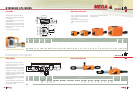
Attachments for pulling and
pushing pistons ( optional )
Single-acting, spring return