


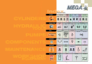

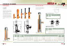
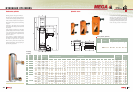
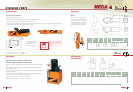
A basic hydraulic configuration consists of a single-acting cylinder, a pump
and a hose. It is really a small machine with the following components:
a) Flow generator = Pump. b) Flexible hose to transmit the oil flow from pump
to cylinder. c) Hydraulic cylinder, consisting of a chamber with inlet for the
oil and a piston to retain the oil and maintain the pressure that raises or
lowers as the oil changes within the chamber. The pressure is
created by resistance to flow. This resistance is the result
of a load. This hydraulic equipment can be used in
virtually all types of industry. From a basic pump
and cylinder set, you can build many
different system configurations by
adding components and
accessories.
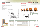
1
2
3
4
5
6
7
8
9
10
11
12
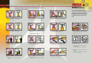
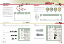
Cylinder
To raise the load.
Page 8
Pump
Creates the hydraulic flow.
Page 24
Hose
Transmits the oil flow.
Page 28
A-5507-M
Male quick coupler
Page 28
A-5507-H
Female quick coupler
Page 28
Gauge
To control pressure.
Page 29
Gauge adapter
To mount the gauge.
Page 29
A-5510
Safety valve
Locks the load on raised cylinder.
Page 30
A-5509
Shutoff valve
Shuts the oil flow and locks
the load on raised cylinder.
Page 30
A-5538
Safety relief valve
Avoids accidental overpressure.
Page 30
Manifold
To distribute the oil flow.
Page 31
12 A-5511
Male connector
To connect different components.
Page 31
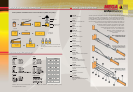
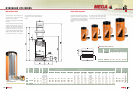
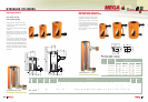
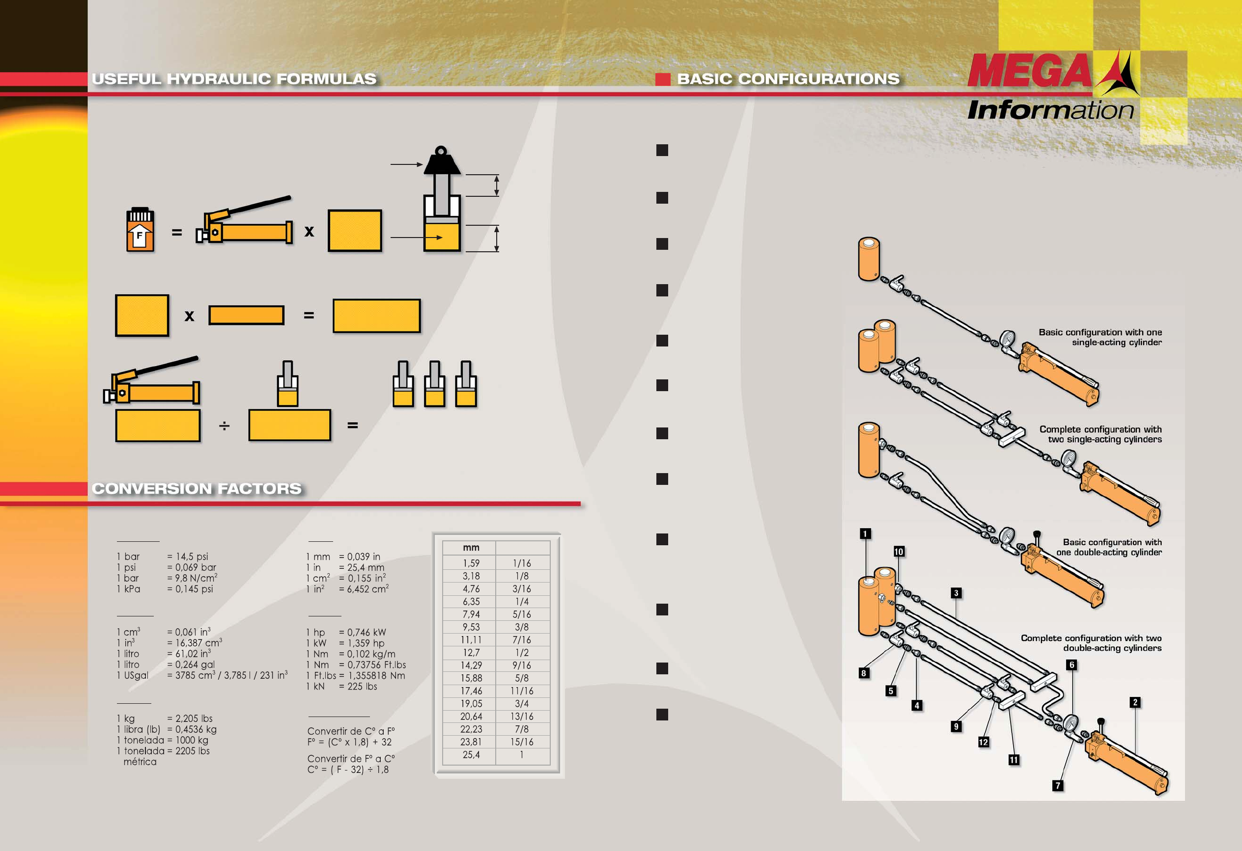
Capacity (kg)
Pressure (kg/cm
2
- psi)
Effective
area
(cm
2
/ in
2
)
Stroke
Volume of oil
(cm
3
/ in
3
)
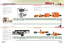
Load
Cylinder
effective area
Stroke
Oil volume
of cylinder
Oil volume
of pump
Oil volume
of cylinder
Number of cylinders that can be used with
one pump.
With long hoses, add 35 cm
3
for each meter
used.
Basic hydraulic calculations for the correct selection of cylinders and pumps.
cm
3
/ in
3
cm / in
cm
2
in
2
Pressure:
Volume:
Weight:
Area:
Others:
Temperature:
Inches
Please note that the dimensions of this catalogue are exact in the metric system ( mm )
and approximate in inches.