


16 17
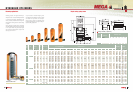
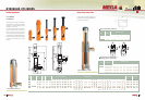
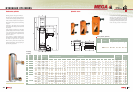
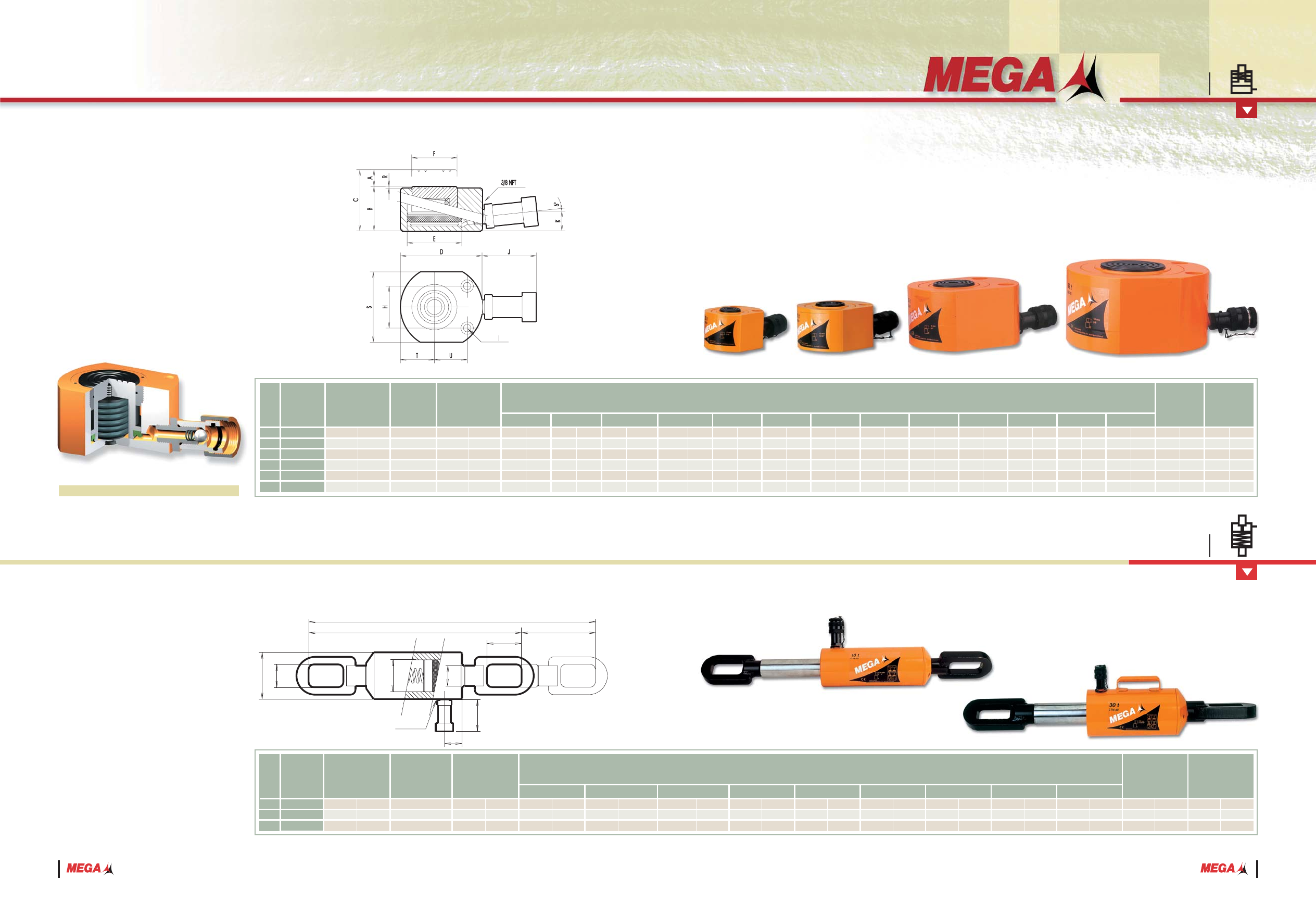
Flat cylinders
CSE Series
HYDRAULIC CYLINDERS
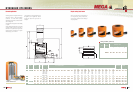
Working pressure: 700 kg/cm
2
/10.000 psi.
All pistons have a salt bath nitriding treatment
to resist corrosion.
Grooved piston ends make optional grooved
saddle unnecessary.
All are equipped with high flow female quick
couplers with dust cap, ref A-5507-H, except
model CSE-5 fitted with a female quick coupler,
ref. A-5506-H.
With mounting holes in the base.
These CSE cylinders have been designed
to combine minimum collapsed height with
optimum stroke.
They are suitable for lifting, clamping,
levelling or positioning jobs where space is
tight.
The spring return piston allows easy removal
from working place.
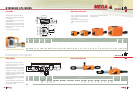
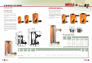
Working pressure: 700 kg/cm
2
/10.000 psi.
All pistons have a hard chrome plating
treatment to resist corrosion.
Equipped with high flow female quick coupler
with dust cap, ref. A-5507-H and carrying handle.
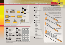
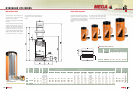
Designed for pulling and tensioning
applications, they can be used in those
operations where two heavy pieces have to be
put one near the other.
They are normally used in industrial assembling,
testing, welding operations of plates or heavy
steel frame works.
They are fitted with clevis eyes on both ends
which are linked to attachments welded onto
the plates to join or weld.
AB
C
X
D W
P
O
3/8 PNT
E
F
127
150
150
5
5
15
/16
5
15
/16
CTN-10
CTN-30
CTN-50
10
30
50
Nominal
capacity
Ref. Stroke
Maximum
capacity
Effective area
tn
A
kN cm
2
in
2
BC DEF0PW
X
cm
3
in
3
Kg.
Oil volume WeightDimensions mm/in.
lbs.
mm. in.
183
725
1085
11,15
44,3
66,2
21,1
48,6
81,4
625
775
920
24
9
/16
30
1
/2
36
7
/32
60
100
125
2
11
/32
3
15
/16
4
15
/16
85
125
155
3
11
/32
4
15
/16
6
1
/8
18
11
/16
24
9
/16
30
5
/16
9,6
22,1
37
98,95
331,8
497,2
14,42
48,34
72,45
2,23
7,49
11,23
475
625
770
42
62
80
1
21
/32
2
7
/16
3
6
/32
35
40
44
1
3
/8
1
9
/16
1
3
/4
70
70
70
2
3
/4
2
3
/4
2
3
/4
40
50
60
1
9
/16
2
2
11
/32
75
100
150
2
15
/16
3
15
/16
5
15
/16
CSE-5
CSE-11
CSE-23
CSE-31
CSE-55
CSE-93
5
11
23
31
55
93
Nominal
capacity
Ref.
Maximum
capacity
Effective area
tn kN cm
2
in
2
BCD TU
cm
3
in
3
Kg.
Oil volume WeightDimensioes mm/in.
lbs.
5
18
37
53
125
212
0,77
2,8
5,73
8,2
19,4
32,8
1,65
3,85
7,05
10,5
20,7
37,9
0,75
1,75
3,2
4,8
9,4
17,2
1
/4
7
/16
7
/16
15
/32
5
/8
5
/8
7,06
15,9
33,08
44,18
78,54
132,73
1,09
2,46
5,12
6,84
12,17
20,57
1
3
/8
1
3
/4
2
1
/8
2
11
/32
2
27
/32
3
15
/32
1
19
/32
2
3
/16
2
9
/16
2
27
/32
3
15
/32
4
3
/32
60
79
98
115
147
180
2
11
/32
3
1
/8
3
7
/8
4
17
/32
5
25
/32
7
3
/32
Stroke
A
mm. in.
13
/16
1
1
/64
1
9
/16
1
13
/16
2
7
/16
3
1
/8
7
/8
1
5
/16
1
7
/16
1
3
/4
2
5
/16
2
15
/16
48,5
109,1
227,7
303,1
539
910,9
20
28
40
47
62
80
22
34
37
44
58
75
6,5
11
11
12
16
16
34
44,5
54
60
72
88
40,5
55,5
65
72
88
104
EFHIJ
K
RS
30
45
65
75
100
130
1
3
/16
1
49
/64
2
9
/16
2
61
/64
3
15
/16
5
1
/64
1
1
/32
1
17
/32
2
1
/8
2
1
/4
3
6
/32
4
9
/64
1
3
/32
1
29
/64
2
2
3
/64
2
3
/4
3
7
/32
1
/4
23
/64
23
/64
7
/16
9
/16
2
11
/32
2
3
/4
2
3
/4
2
3
/4
2
3
/4
2
3
/4
11
/16
15
/16
15
/16
15
/16
15
/16
15
/16
3
/64
3
/64
3
/64
3
/64
3
/64
3
/64
1
5
/8
2
13
/64
3
1
/8
3
11
/16
4
7
/8
6
5
/16
26
39
54
57,15
80
105
28
37
50
52
70
76
5,5
6,6
9
9
11
14
60
70
70
70
70
70
17
23
23
23
23
23
41
56
80
94
124
160
1
1
1
1
1
1
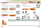
Cross section view
CTN Series
Pulling cylinders
HYDRAULIC CYLINDERS
Single-acting, spring-return
Single-acting, spring return