JOBNAME: No Job Name PAGE: 49 SESS: 1 OUTPUT: Thu Aug 3 11:45:36 2006
/ford_pdm/ford/own2002/mbs/og
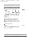
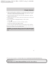
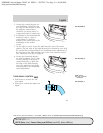
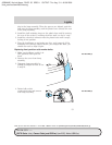
5. Locate the vertical adjuster for
each headlamp. Adjust the aim
by usinga4mmwrench to turn
the adjuster control either
clockwise (to adjust down) or
counterclockwise (to adjust up).
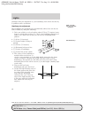
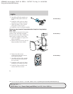
6. In addition to the horizontal line
marked in step 2, a pair of
vertical lines (5) must be
marked at the center line of the
headlamps on the wall or
screen.
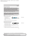
7. On the wall or screen, locate the high intensity area of the beam
pattern. The left edge of the high intensity area should be even with
the vertical line corresponding to the headlamp under adjustment. If
the left edge of the high intensity area is not even with the vertical
line, follow the next step to adjust it.
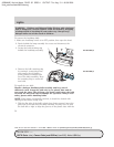
8. Locate the horizontal adjuster
for each headlamp. Usea4mm
wrench, turning it clockwise or
counterclockwise, to place the
left edge of the high intensity
area even with the vertical line
corresponding to the headlamp
under adjustment.
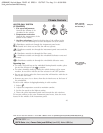
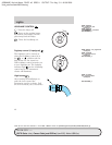
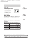
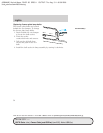
TURN SIGNAL CONTROL
• Push down to activate the left
turn signal.
• Push up to activate the right turn
signal.
CIMS #54764
com_turn_indicator
itdseq=46
art=mbscf406_a
art=mbscf407_a
art=rancf324_a
REVIEW COPY ——
2007 B-Series (mbs), Owners Guide (post-2002-fmt) (own2002), Market: USA (fus)
PAGE: 49 OP: root EDIT SESSION: 1 DATE: AUG 3 2006 at 11:45
JOB: @ibm2/ford_pdm/CLS_ford/GRP_own2002/JOB_mbs/DIV_og
Lights
49


