


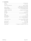

201/203 Series Page 8 of 20
regulators and large internal diameter plumbing help to make the system more stable. The pressure
drop between the regulator and the instrument due to line resistance should be minimized. The
differential pressure across the unit should be less than 6” of H2O at maximum flow.
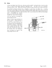
There are two 8-32 threaded holes, 0.25” deep, located on the bottom of the base that can be used to
secure it to a mounting bracket, if desired (screws provided). Other holes for special mounting can
be added to the end cap as desired.
The standard inlet and outlet fittings for the 201/203 are 0.5” and 0.75” Swagelok (optional VCR or
VCO fittings). The O-rings for the end cap and the sensor are Viton (optional Kalrez or Neoprene).
It is suggested that all connections be checked for leaks after installation. This can be done by
pressurizing the instrument (do not exceed 500 psig unless the flow meter is specifically rated for
higher pressures) and applying a diluted soap solution to the flow connections rated for higher
pressures) and applying a diluted soap solution to the flow connections.
2.5. Electrical Connections
If a power supply from Hastings Instruments is used, installation consists of connecting the HFM-
201/HFC-203 series cable from the “D” connector on the rear of the power supply to the “D”
connector on the top of the flow meter. If a different power supply is used, follow the instructions
below when connecting the flow meter.
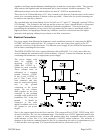
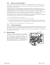
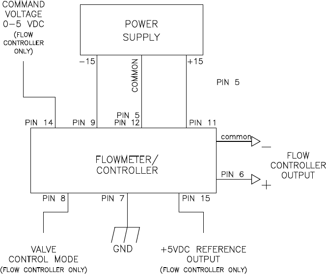
This HFM-201/HFC-203 series requires Hastings cable #AF-8AM. Use of any other cable can
severely damage the instrument and void the warranty. Figure 2.1 shows the schematic layout for
connecting the instrument to an appropriate power supply.
The power supply used
must be capable of
supplying +15VDC at
50mA and -15VDC at -
200mA for each controller.
These voltages must be
referenced to a common
ground. Connect -15VDC
to pin 9 and +15VDC to
pin 11. Pins 5 and 12 are
both commons and they
must be connected together
and to the ground
connection at the power
supply. Do not connect
them together at the flow
controller as the resulting
crosstalk could result in flow
instabilities. Pin 7 is the case
ground. It should be
connected to the cable
shield if available and to the
AC ground to the power
supply.
Pin 6 is the output signal from the flow controller. This output will be 0-5VDC, 5VDC being 100%
of rated or full flow. Pin 14 is the command input. This should be a 0-5VDC signal and must be free
of spikes or other electrical noise, as these will generate false flow commands that the controller
would attempt to flow. Pin 15 is a well regulated +5.00VDC output reference. The reference is
designed to provide the command signal for pin 14 by connecting one end of a potentiometer to pin
15 and the other end to ground. The center lead would then be connected to pin 14.