


201/203 Series Page 11 of 20
2.6.8. Response to Command Changes
The response of the control circuit to changes to the command signal is set at the factory for fast,
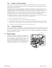
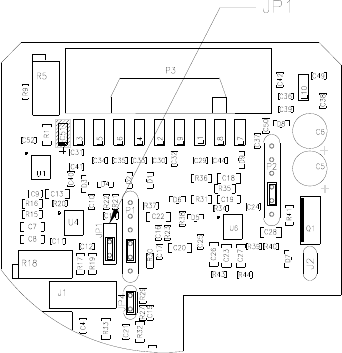
stable response. Should it be necessary, the response is adjustable using the jumper labeled “JP4,”
located in the center of PC-828.
The fastest response to command changes is obtained when JP4 is covered by the jumper. This
setup allows large overshoot and undershoot swings in the actual flow rate while the control circuit is
establishing control at the new command point. The slowest response to command changes is
obtained when JP4 is not covered by a jumper. This setup results in no overshoot or undershoot in
the actual flow rate as the controller circuit establishes control at the new command point.
To adjust the response, you need a means of producing a step change in the command voltage from
10% of full scale to 100% of full scale. Follow the steps outlined below:
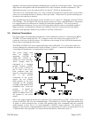
1) Cover the pins of JP4 with a jumper. (see fig. 2.2)
2) Set the command voltage to 10% of full scale. Allow the flow to stabilize.
3) Step change the command voltage to 100%, and observe the flow through the controller. If the overshoot
is too large, remove the jumper. Reset the command voltage to 10%, and allow the controller to stabilize.
4) To prevent loss of the unused jumper, place it over one pin only on JP4.
2.6.9. Operating Temperature
For proper operation, the combination of ambient temperature and gas temperature must be such
that the Flowcontroller temperature remains between 0 and 500C. Most accurate measurement of
flow will be obtained if the flow controller is re-zeroed at operating temperature, as temperature
shifts result in some zero offset.
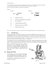
2.7. Range Changing:
The range of the flow controller can be changed in
the field if recalibration facilities are available. The
flow controller may require a different orifice, which
can be purchased separately from the factory. A
listing of the orifices available and their flow rates
can be found in Section 5.0. The instructions to
change the flow range can be found in Section 4.6.