


201/203 Series Page 16 of 20
ACTION: Shut off gas supply and power supply. Remove cover and PC board from unit. Remove
sensor assembly and examine. If sensor has evidence of plugging, clean or replace as applicable
SYMPTOM: Flow controller oscillates.
CAUSE: Flow controller not adjusted for the dynamics of the flow system.
ACTION: Check upstream and downstream pressures. The gas supply regulator should not have
excessive lockup when flow shuts off. Also ensure that there is not a large drop in pressure between
the regulator and the instrument due to line resistance. Oscillations can also be caused if a large flow
restriction is pneumatically close to the downstream end of the flow controller. The differential
pressure across the unit must be between 10-50 psig.
SYMPTOM: Little or no flow, even with Valve Override switch OPEN.
CAUSE: Plugged orifice.
ACTION: Verify the presence of a 10-50 psig pressure across the instrument. If present, shut off
gas supply and power supply. Remove orifice per Section 4.9. Examine orifice. If plugged, clean or
replace as applicable. Reassemble valve.
SYMPTOM: Flow meter reads other than 0.00 VDC with no flow, or there is a small flow when
flow meter reads 0.00 VDC.
CAUSE: ZERO potentiometer is out of adjustment.
ACTION: Shut off all flow. Adjust ZERO potentiometer until output reads 0.00 VDC.
SYMPTOM: Flow meter out of calibration and nonlinear.
CAUSE: Leaks in gas inlet or outlet fittings.
ACTION: Check all fittings for leaks by placing soap solution on all fittings between gas supply and
final destination of gas. Check flow meter for leaks. Replace “O” rings if required or recalibrate as
necessary.
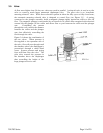
4.3. Adjustments
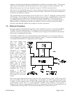
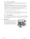
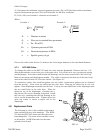
4.3.1. Calibration Procedure: (Figure 4.1)
NOTE: Adjusting the SPAN pot will require the use of a
calibration reference in Step 5.
1) Connect power cable to D connector as specified in Section
2.7. Allow instrument to warm up for 30 minutes with 10%
flow and instrument in AUTO position.
2) Set ZERO (R19) potentiometer for 0.000 VDC output.
3) Turn on gas supply to inlet of instrument. Put Valve Override
switch into CLOSE position. Adjust the orifice underneath
controller to obtain zero flow. Put Valve Override switch into
AUTO. Ensure that full range flow can still be obtained at
minimum inlet pressure.
SPAN
ZERO
FIG 4.1