


201/203 Series Page 7 of 20
2. Installation and Operation
This section contains the necessary steps to assist in getting a new flow meter/controller into
operation as quickly and easily as possible. Please read the following thoroughly before attempting
to install the instrument.
2.1. Receiving Inspection
Carefully unpack the Hastings 201/203 series instrument and any accessories that have also been
ordered. Inspect for any obvious signs of damage to the shipment. Immediately advise the carrier
who delivered the shipment if any damage is suspected. Check each component shipped with the
packing list. Insure that all parts are present (i.e., flow meter, power supply, cables, etc.). Optional
equipment or accessories will be listed separately on the packing list. There may also be one or more
OPT-options on the packing list. These normally refer to special ranges or special gas calibrations.
They may also refer to special helium leak tests, or high pressure tests. In most cases, these are not
separate parts, but special options or modifications built into the flow meter.
2.2. Power Requirements
The HFM-201/HFC-203 series requires ±15 VDC @ ±50 mA (HFM-201) +50 mA, -200 mA
(HFC-203)for proper operation. The supply voltage should be sufficiently regulated to no more
than 50 mV ripple. The supply voltage can vary from 14.0 to 16.0 VDC. Surge suppressors are
recommended to prevent power spikes reaching the instrument. The Hastings power supply
described in Section 1.4.2 satisfies these power requirements.
The HFM-201/HFC-203 series instruments have an integral 5 VDC ref. source. This stable voltage
is on pin 15 of the “D” connector and may be used for the command voltage on the controller
(HFC-203).
2.3. Output Signal
The standard output of the flow meter is a 0-5 VDC signal proportional to the flow rate. In the
Hastings power supply the output is routed to the display, and is also available at the terminals on
the rear panel. If a Hastings supply is not used, the output is available on pin 6 of the “D” connector
and is referenced to pin 5. It is recommended that the load resistance be no less that 2kW. If the
optional 4-20 mA output is used, the load impedance must be selected in accordance with Section
1.3.
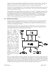
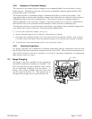
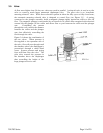
2.4. Mechanical Connections
The flow meter may be mounted in any position as long as the direction of gas flow through the
instrument follows the arrow marked on the bottom of the flow meter case label. The preferred
orientation is with the inlet and outlet fittings in a horizontal plane (if operating with a dense gas or at
high pressures the instrument must be installed horizontally). When mounted in a different
orientation the instrument should be re-zeroed at zero flow with the system pressurized to the
expected operating pressure.
The smallest of the internal passageways in the 201/203 series is the diameter of the sensor tube,
which is 0.0125”(0.31 mm), so the instrument requires adequate filtering of the gas supply to
prevent blockage or clogging of the tube.
The pressure regulator and the plumbing upstream must be of sufficient size to minimize changes in
the upstream pressure. When switching from full flow to zero flow, the inlet pressure of instrument
should rise to no more that 30% above the inlet pressure at full flow. In general, high capacity