


4
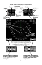
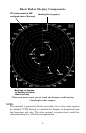
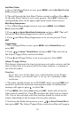
Basic Radar Display Components
Your unit has three electronic bearing
lines and three variable range markers.
An enlarged example of EBLs and
VRMs is on the next page.
PPI Position
status
Display
mode
Range
Range Ring
Interval
Echo Trail
status
A
nti-Rain
Clutter
A
nti-Sea
Clutter
Radar Echo
Expansion
status
Interference
Rejection
status
Ga
in l
e
v
e
l
Electronic Bearing Line position
for EBLs 1, 2 and 3. Highlighted
in white, EBL 2 is the active
bearing line.
V
ariable Range Marker position
for VRMs 1, 2 and 3. Highlighted
in white, VRM 2 is the active
range marker.
Electronic
Bearing
Lines
V
ariable
Range
Markers