


5
Gate Control
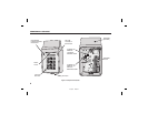
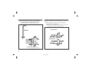
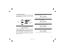
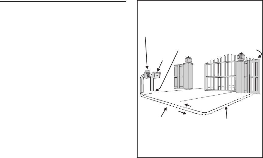
Refer to Figure 5 for an outline of a typical gate installation.
❑ Route four wires between the gate and the keypad (two for
power, two for control).
❑ Connect the gate operator’s auxiliary or radio power output
terminals to the keypads POWER input terminals (observe
wiring polarity).
❑ Connect the gate operator’s OPEN terminals to the keypad’s
Relay #1 COMMON & N.O. terminals.
☞ NOTE: For operator wiring specifi cs, refer to the gate
operator’s wiring diagram.
❑ If a request-to-enter pushbutton or fi re access keyswitch is
going to be used, route two wires from the keypad to the
normally open switch. Connect the wires to the normally
open switch and to the keypad’s REQUEST-TO-ENTER and
COMMON terminals.
❑ If an inhibit switch or timer is going to be used, route two
wires from the keypad to the inhibit switch or timer relay.
Connect the inhibit switch/timer terminals to the keypad’s
INHIBIT and COMMON terminals.
☞ NOTE: If the INHIBIT input is going to be used, it must be
programmed to select that input type. See the Programming
Options section of this manual
AKR-1
KEYPAD
FIRE
ACCESS
KEYSWITCH
2 WIRES FROM OPERATOR
FOR AKR-1 POWER
GATE
OPERATOR
(BEHIND GATE)
2 WIRES FROM AKR-1
TO TRIGGER GATE OPEN
2 WIRES FOR
REQUEST-TO-ENTER
Figure 5. Gate Installation
217350 D IMAGE 7