


8
Adding a New Entry Code
Press: 0 1 # Code # Code # Relay #
Code = The new entry code: 1-999999, depending on code length
Relay = Relay output entry code will activate:
1 = Relay #1 2 = Relay #2 3 = Both Relays
The yellow indicator will fl ash quickly while the AKR-1 searches its memory for
available space and duplicate entries. The green indicator will light when the new
code is stored.
If the new entry code chosen is already being used for another entry code, the red
indicator will light. A new unique code needs to be entered.
☞ NOTE: Leading zeros (zeros before the code number, i.e. 0001) do not need to be entered
when programming a new entry code. The AKR-1 will internally add any zeros to fi ll all
digits determined by the entry code length setting. Leading zeros will have to be entered by
the user when entering their code to gain access.
Erasing a Single Entry Code
Press: 0 2 # Code # Code #
Code = The entry code to delete.
The yellow indicator will fl ash quickly while the AKR-1 searches its memory for the
code to erase. The green indicator will light when the code is erased.
Erasing All Entry Codes
★ WARNING: Performing this command will remove all
entry codes from the memory.
Press: 9 7 # 0 0 0 0 0 0 # 0 0 0 0 0 0 #
☞ NOTE: The green indicator will light while the memory is being erased. This may take up
to 15 seconds.
Changing the 6-Digit Master Programming Code
Press: 9 8 # Master Code # Master Code #
Master Code = The new 6-digit Master Programming Code
New master code: _____________________
PROGRAMMING OPTIONS
There are several AKR-1 programming options. For most installations, the factory
set default options are suffi cient. The keypad must be in Programming Mode to
make these changes.
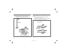
Programming AKR-1 to Hold the Output
Linear’s AccessKey products have a programmable “Toggle Mode” available for
each relay and solid-state output. When an output is programmed for Toggle Mode,
the output alternates from OFF to ON or from ON to OFF each time it is activated.
The rules for a toggle output are:
• If the output is OFF, it will turn ON and stay on until the next activation.
• If the output is ON, it will turn OFF and stay off until the next activation.
Typical Programming
With the unit in Program Mode, set the Auxiliary Relay (Relay #2) output to Toggle
Mode using the following keystrokes:
Press: 2 2 # 9 9 #
22 = Programming Step; 99 = Toggle Mode
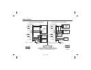
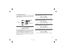
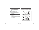
Program all normal entry codes to use the Main Relay (Relay #1), and only
Relay #1 as the output relay. Program the code(s) that you want to use to hold the
output for an indefi nite period to the Auxiliary Relay (Relay #2). See the following
example that sets entry codes 1234 for normal and 5678 for toggle operation.
Press: 0 1 # 1 2 3 4 # 1 2 3 4 # 1 #
01 = Programming Step; 1234 = Entry Code;
1 = Main Relay
Press: 0 1 # 5 6 7 8 # 5 6 7 8 # 2 #
01 = Programming Step; 5678 = Entry Code;
2 = Auxiliary Relay
217350 D IMAGE 10
5678
TOGGLE
ENTRY CODE
1234
NORMAL
ENTRY CODE