


3
Keypad Wiring
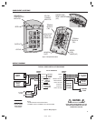
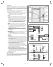
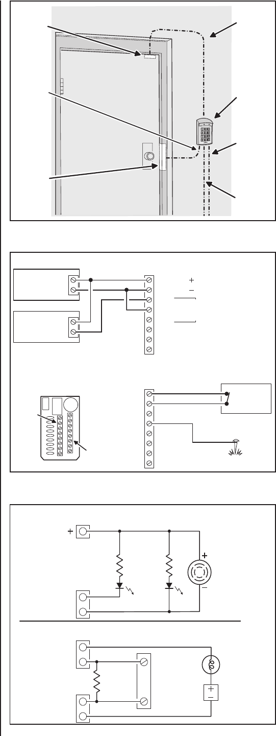
See Figure 7 for an example of a basic door installation. The
keypad is mounted adjacent to the door. An electric door strike
is mounted in the door jamb to release the door lock. A magnetic
switch is mounted on the top of the door jamb for detecting when
the door is open.
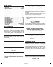
Use the following steps to wire the keypad. Refer to the wiring
diagram shown in Figure 8 to assist in the wiring.
☞ NOTE: Up to 500 feet of 18 AWG wire can be run for power,
use larger wire for longer runs. Use 22 AWG or larger
(depending on the load) for other connections.
OUTPUT
❑ Install a low voltage electric door strike for unlocking the
door.
❑ Route two wires between the door strike and the keypad
box. Connect one of the door strike wires to the keypad’s
MAIN RELAY N.O. terminal (TB2 #3). Connect the other
door strike wire to the keypad’s AC/DC + terminal (TB2 #1).
Connect a wire between the keypad’s AC/DC - terminal
(TB2 #2) and the MAIN RELAY COM terminal (TB2 #4).
POWER
❑ Choose a location for the power supply or transformer.
❑ Route two wires between the power supply and the keypad
box. Connect the power supply’s output terminals to the
keypad’s AC/DC input terminals (TB2 #1 & #2). Observe
wiring polarity if using DC.
✦ CAUTION: If the unit is AC powered, make sure the
secondary of the system transformer is isolated from
earth ground.
EARTH GROUND
❑ To avoid damage to the unit from static discharges, connect
the EARTH GROUND terminal (TB1 #5) to a good earth
grounding point. Suggested wiring size is 18 AWG for earth
ground.
SENSE INPUT
☞ NOTE: SENSE terminal (TB1 #8) can be programmed for
either a door sense or inhibit input. Both features cannot be
used at the same time.
❑ To use the door sense feature to detect forced entry or door
ajar conditions, install a normally closed door switch on the
door and route two wires from the switch to the keypad box.
Connect the door switch to the keypad’s SENSE terminal
(TB1 #8) and COM terminal (TB1 #7).
❑ If an inhibit switch or timer is going to be used for
temporarily disabling the keypad, route two wires from
the switch or timer to the keypad box. Connect the inhibit
switch/timer normally open terminals to the keypad’s SENSE
(TB1 #8) and COM (TB1 #7) terminals.
REQUEST-TO-EXIT INPUT (wiring shown on Page 1, Figure 2)
❑ If a request-to-exit pushbutton is going to be used, route two
wires from the keypad box to a normally open pushbutton
mounted on the secure side of the door. Connect the wires
to the pushbutton and to the keypad’s EXIT (TB1 #6) and
COM (TB1 #7) terminals.
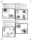
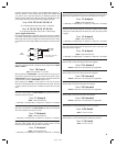
Solid State Outputs
The two solid state outputs (Output #3 & Output #4) can be
programmed to activate during various conditions. These outputs
can be used to activate indicators or sounders. See Figure 9 for
wiring examples using the solid state outputs.
222162 B IMAGE 5
Figure 7. Basic Door Installation
1 WIRE
TO EARTH
GROUND
DOOR
SENSE
SWITCH
ELECTRIC
DOOR
STRIKE
AK-2W
KEYPAD
2 WIRES
FOR DOOR
STRIKE
2 WIRES
FOR DOOR
SENSE
SWITCH
2 WIRES
FROM
POWER
SUPPLY
Figure 8. Basic Door Installation Wiring
1 - AC OR DC
2 - AC OR DC
3 - N.O.
4 - COM
5 - N.C.
6
7
8
MAIN
RELAY
5 AMPS MAX.
TERMINAL
BLOCK 2
12-24 VOLT
AC OR DC
POWER
SUPPLY
ELECTRIC
DOOR
STRIKE
SENSE - 8
COM - 7
6
EARTH GROUND - 5
4
3
2
1
TERMINAL
BLOCK 1
GROUND
STAKE
N.C. DOOR
SENSE
SWITCH
TERMINAL
BLOCK 1
(TB1)
TERMINAL
BLOCK 2
(TB2)
AK-2W REAR VIEW
1
4
OUTPUT #3
OUTPUT #4
AK-2W
POWER
1K Ω
LED
1K Ω
LED
ELECTRONIC
BEEPER
OUTPUT #3 LIGHTS A LAMP POWERED FROM AN EXTERNAL SOURCE
OUTPUT #4 TRIGGERS A NORMALLY OPEN ALARM PANEL ZONE
OUTPUT #3
OUTPUT #4
EACH
OUTPUT
100 mA
MAXIMUM
ALARM PANEL
N.O. ZONE
COMMON
END-OF-LINE
RESISTOR
POWER
SOURCE
LOW VOLTAGE
LAMP
1
3
2
3
2
TERMINAL
BLOCK #1
TERMINAL
BLOCK #2
OUTPUT #3 LIGHTS AN LED
OUTPUT #4 LIGHTS AN LED AND SOUNDS A BEEPER
OUTPUT #4 COM
OUTPUT #3 COM
EXAMPLE #2
EXAMPLE #1
Figure 9. Using Solid State Outputs