


CONTENTS
INTRODUCTION
Linear’s AK-2W is a digital keyless entry system designed for access control
applications. The keypad is housed in a rugged, die-cast metal enclosure and is
designed to be mounted in a single-gang electrical box. The die-cast keys have
bright, easy-to-read yellow graphics.
Up to 480 entry codes, from 1 to 6 digits in length, can be programmed. They can
activate either, or both, of the relay outputs. The “anti-passback” feature prevents
using the same code again before the programmed time elapses.
All system indicators and lights are long-lasting, solid-state LEDs. Two indicators
show the status of the entry system. The left indicator lights red to indicate power,
then turns green when access is granted. The right indicator lights yellow when
the keypad is in “lockout” condition (from too many incorrect code entries). The
keypad’s courtesy light dimly illuminates the keys at all times. The courtesy light
brightly illuminates the keys for two minutes after any key is pressed. An internal
sounder beeps when each key is pressed. An internal jumper sets the sounder
volume high or low.
The SENSE input can be used two ways. If programmed for “door sense” the
input is wired to a normally closed switch on the door to detect when the door is
open or closed. Forced entry or door ajar situations can then be detected. Using
door sense, the “Auto-relock” feature will prevent “tailgating” by turning off the
Main Relay output immediately when the door is closed after access has been
granted. If the SENSE input is programmed for “inhibit”, the input can be wired
to a “service” switch or automatic timer that will disable the Main Relay when
required.
The REQUEST-TO-EXIT input can be wired to a pushbutton to provide
codeless activation of Main Relay, Auxiliary Relay, Output #3, or Output #4
(programmable).
The ALARM SHUNT output activates when access is granted. This output can
be wired to shunt alarm contacts on the access door/gate to prevent triggering of
an alarm when authorized access occurs.
The AK-2W is powered from a 12-24 Volt AC or DC source. Power can be obtained
from the access device or a separate power supply. The EEPROM memory
retains all entry codes and programming, even without power. An internal jumper
is provided to reset the master code. The Main Relay has a 5 Amp capacity.
The Auxiliary Relay has a 1 Amp capacity. Two solid state outputs, capable of
switching 100 mA to common, are programmable to signal forced entry, door ajar,
lockout, alarm circuit shunting, request-to-exit, and keypad active conditions.
FEATURES
✓ WEATHER RESISTANT DESIGN
or outdoor installation
✓ KEYPAD PROGRAMMABLE
No programmer required
✓ 480 ENTRY CODE CAPACITY
Ideal for small & medium traffi c installations
✓ 1-6 DIGIT ENTRY CODE LENGTH
Flexible code length for different applications
✓ 4 INDEPENDENT OUTPUTS (TIMED/TOGGLED)
Each output’s action is programmable
✓ 4 INDEPENDENT TIMERS
Each output’s activation time is programmable
✓ TWO FORM “C” (N.O. & N.C) RELAY CONTACTS
Main Relay 5-Amp @ 28 VDC capacity,
Auxiliary Relay 1-Amp @ 28 VDC capacity
✓ EACH ENTRY CODE CAN ACTIVATE EITHER OR BOTH RELAYS
Specifi c entry codes can grant access to different doors
✓ TWO SOLID STATE OUTPUTS
Auxiliary outputs can indicate access status on external devices
✓ TWO STATUS INDICATORS (2-COLOR RED/GREEN & YELLOW)
Displays access, lockout, and programming information
✓ WHITE SOLID-STATE LED COURTESY LAMP
Low level at idle, high level during keypad use
✓ PIEZO SOUNDER (TWO SELECTABLE VOLUME LEVELS)
Programmable for beeps during key presses and output activations
✓ TIMED ANTI-PASSBACK
Disables entry code for a programmed time after use
✓ AUTO-RELOCK
Releases the main relay as soon as the door shuts
✓ KEYPAD LOCKOUT
Locks the keypad after too many incorrect entries
✓ TACTILE KEY FEEL
Assures complete key presses
✓ DOOR SENSE INPUT
For sensing door position to control auto-relock and door-ajar features
✓ INHIBIT INPUT
For temporarily disabling access with a timer or switch
✓ REQUEST-TO-EXIT INPUT
For codeless activation with a pushbutton
✓ KEYPAD CAN BE POWERED FROM 12-24 VOLTS AC OR DC
Power can be supplied from a transformer, battery, or power supply
222162 B IMAGE 2
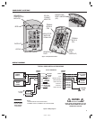
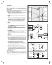
COMPONENT LOCATIONS . . . . . . . . . . . . . . . . . . . . . . . . . . . . . . . . . . . . . . . 1
WIRING DIAGRAM . . . . . . . . . . . . . . . . . . . . . . . . . . . . . . . . . . . . . . . . . . . 1
INSTALLATION . . . . . . . . . . . . . . . . . . . . . . . . . . . . . . . . . . . . . . . . . . . . . . . 2
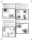
Opening the Keypad . . . . . . . . . . . . . . . . . . . . . . . . . . . . . . . . . . . . . . . 2
Install the Electrical Box and Mounting Plate . . . . . . . . . . . . . . . . . . . . . . 2
Final Keypad Installation . . . . . . . . . . . . . . . . . . . . . . . . . . . . . . . . . . . . 2
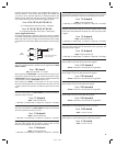
Keypad Wiring . . . . . . . . . . . . . . . . . . . . . . . . . . . . . . . . . . . . . . . . . . . 3
Solid State Outputs . . . . . . . . . . . . . . . . . . . . . . . . . . . . . . . . . . . . . . . . 3
FACTORY DEFAULTS . . . . . . . . . . . . . . . . . . . . . . . . . . . . . . . . . . . . . . . . . . . 4
BASIC PROGRAMMING . . . . . . . . . . . . . . . . . . . . . . . . . . . . . . . . . . . . . . . . 4
PROGRAMMING OPTIONS . . . . . . . . . . . . . . . . . . . . . . . . . . . . . . . . . . . . . . 4
RESETTING KEYPAD . . . . . . . . . . . . . . . . . . . . . . . . . . . . . . . . . . . . . . . . . . . 6
Master Reset . . . . . . . . . . . . . . . . . . . . . . . . . . . . . . . . . . . . . . . . . . . . 6
Resetting the Master Code . . . . . . . . . . . . . . . . . . . . . . . . . . . . . . . . . . . 6
AK-2W OPERATION . . . . . . . . . . . . . . . . . . . . . . . . . . . . . . . . . . . . . . . . . . . 6
SPECIFICATIONS . . . . . . . . . . . . . . . . . . . . . . . . . . . . . . . . . . . . . . . . . . . . . . 6
LINEAR LIMITED WARRANTY . . . . . . . . . . . . . . . . . . . . . . . . . . . . . . . . . . . . 6
IMPORTANT !!! . . . . . . . . . . . . . . . . . . . . . . . . . . . . . . . . . . . . . . . . . . . . . . 6
FCC NOTICE . . . . . . . . . . . . . . . . . . . . . . . . . . . . . . . . . . . . . . . . . . . . . . . . . 6