


2
INSTALLATION
Before installing the keypad, the unit must be partially disassembled
to access the mounting plate.
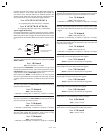
Opening the Keypad
The keypad assembly is secured with two tamper-resistant screws.
Refer to Figure 3 for disassembly details.
❑ Use the special allen wrench (supplied) to remove the two
tamper-resistant screws.
❑ Separate the mounting plate from the keypad assembly.
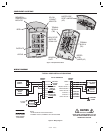
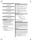
Install the Electrical Box and Mounting Plate
The keypad is designed to fi t into a single-gang electrical box. The
box must be deep enough to accomodate the protective plastic
enclosure. Select a location near the controlled door and choose
a convenient height for the keypad. Be sure there is good wiring
accessibility for the unit’s power and the output to the door strike
or access device.
❑ Install the electrical box in the wall.
❑ Place gasket on protective plastic enclosure and insert into
electrical box.
❑ Screw the mounting plate onto the electrical box (see
Figure 4).
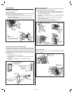
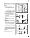
Final Keypad Installation
After wiring the keypad (see next page), complete the installation
by securing the keypad to the mounting plate.
❑ If a lower beeper sound level is required, before installing
the keypad, remove Jumper JP1 (place the jumper block on
one pin to save the jumper).
❑ Hook the keypad assembly onto the mounting plate tab (see
Figure 5).
❑ Use the special allen wrench (supplied) to install the two
tamper-resistant screws.
❑ Fit the bottom tab on the faceplate into the slot on the
keypad then snap the top of the faceplate in.
Faceplate Removal
Refer to Figure 6 for details on removing the faceplate if keypad
service is required.
HOOK THE KEYPAD ASSEMBLY
ONTO THE MOUNTING PLATE
1
2
3
4
INSTALL THE
TWO SCREWS
FIT THE BOTTOM TAB OF
THE FACEPLATE INTO THE
SLOT ON THE KEYPAD
SNAP THE TOP
OF THE KEYPAD
INTO PLACE
Figure 5. Connecting the Keypad to the Mounting Plate
222162 B IMAGE 4
1
2
REMOVE THE
TWO SCREWS
SEPARATE THE
MOUNTING PLATE AND PLASTIC
ENCLOSURE FROM THE KEYPAD
MOUNTING
PLATE
Figure 3. Opening the Keypad
INSTALL A SINGLE-GANG
ELECTRICAL BOX AT THE
PROPER LOCATION
FOR THE KEYPAD
ATTACH THE MOUNTING
PLATE TO THE
ELECTRICAL BOX
MAKE SURE THE
TAB IS UP
MOUNTING
PLATE
PLACE GASKET ON
PROTECTIVE PLASTIC
ENCLOSURE AND
INSERT INTO
ELECTRICAL BOX
1
2
3
(NOTE DIRECTIONAL
ARROW ON PLASTIC)
Figure 4. Installing the Mounting Plate
PRY UP ON THE
FACEPLATE HERE
1
2
REMOVE THE
FACEPLATE
Figure 6. Removing the Faceplate