


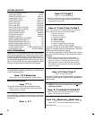
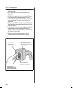


Gate Control
Route four wires between the gate and the keypad (two for
power, two for control).
Connect the gate operator’s auxiliary or radio power output
terminals to the keypads POWER input terminals (observe
wiring polarity).
Connect the gate operator’s OPEN terminals to the
keypad’s Relay #1 COMMON & N.O. terminals.
☞NOTE: For operator wiring specifics, refer to the gate
operator’s wiring diagram.
If a request-to-enter pushbutton or fire access keyswitch
is going to be used, route two wires from the keypad to the
normally open switch. Connect the wires to the normally
open switch and to the keypad’s REQUEST-TO-ENTER
and COMMON terminals.
If an inhibit switch or timer is going to be used, route two
wires from the keypad to the inhibit switch or timer relay.
Connect the inhibit switch/timer terminals to the keypad’s
INHIBIT and COMMON terminals.
☞NOTE: If the INHIBIT input is going to be used, it must be
programmed to select that input type. See the Programming
Options section of this manual.
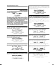
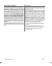
Door Control
Install a low voltage electric door strike for unlocking the
door.
Choose a location for the power supply or transformer.
Route two wires between the power supply and the
keypad. Connect the power supply’s output terminals to
the keypad’s POWER input terminals (observe wiring
polarity).
Route two wires between the door strike and the keypad.
Connect one of the door strike wires to the keypad’s Relay
#1 N.O. terminal. Connect the other door strike wire to the
keypad’s POWER
+
terminal. Connect a wire between the
keypad’s POWER
- terminal and the Relay #1 COMMON
terminal.
If a request-to-enter pushbutton or fire access keyswitch
is going to be used, route two wires from the keypad to the
normally open switch. Connect the wires to the normally
open switch and to the keypad’s REQUEST-TO-ENTER
and COMMON terminals.
To use the door sense feature to detect forced entry or
door ajar conditions, install a normally closed door switch
on the door and route two wires from the switch to the
keypad. Connect the door switch to the keypad’s DOOR
SENSE and COMMON terminals.
If an inhibit switch or timer is going to be used, route two
wires from the switch or timer to the keypad. Connect the
inhibit switch/timer terminals to the keypad’s INHIBIT and
COMMON terminals.
☞NOTE: Either door sense or inhibit can be used. Both features
cannot be used at the same time.
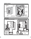
AK-11
KEYPAD
FIRE
ACCESS
KEYSWITCH
2 WIRES FROM OPERATOR
FOR AK-11 POWER
GATE
OPERATOR
(BEHIND GATE)
2 WIRES FROM AK-11
TO TRIGGER GATE OPEN
2 WIRES FOR
REQUEST-TO-ENTER
Figure 5. Gate Installation
FROM
POWER
SUPPLY
DOOR
SENSE
SWITCH
ELECTRIC
DOOR
STRIKE
AK-11
KEYPAD
2 WIRES
FOR DOOR
STRIKE
2 WIRES
FOR DOOR
SENSE
2 WIRES
FOR
POWER
Figure 6. Door Installation
5