


CONTENTS
INTRODUCTION
Linear’s AK-11 is a digital keyless entry system designed for
access control applications. The keypad is housed in a rugged
cast aluminum enclosure that can be mounted to a pedestal or
bolted directly to a wall. The die-cast keys have bright,
easy-to-read yellow graphics.
Up to 480 entry codes, from 1 to 6 digits in length, can be
programmed. They can activate either, or both, of the relay
outputs. Relay #1 has a 5 Amp capacity. Relay #2 has a 1 Amp
capacity.
Two LED indicators show the status of the entry system. The left
LED lights red to indicate power, then turns green when access
is granted. The right LED lights yellow when the keypad is in
“lockout” condition (from too many incorrect code entries). The
keypad’s courtesy light can be always off, always on or be
programmed to illuminate from 1-4 minutes after any keypress
(default 2 minutes). An internal sounder beeps when each key is
pressed.
The DOOR SENSE/INHIBIT input can be used two ways. If
programmed for “door sense”, a switch on the door detects
forced entry or door ajar situations. If programmed for “inhibit”,
the input can be wired to a “service” switch or automatic timer
that will disable the Relay #1 when required.
The REQUEST-TO-ENTER input can be wired to a pushbutton
or fire access keyswitch to provide codeless entry for authorized
personnel. The “anti-passback” feature prevents using the same
code twice before the programmed time elapses.
The ALARM SHUNT output activates when access is granted.
This output can be wired to shunt alarm contacts on the access
door/gate to prevent triggering of an alarm when authorized
access occurs.
Two solid state outputs, capable of switching 100 mA to common,
are programmable to signal forced entry, door ajar, lockout,
alarm circuit shunting, request-to-enter, and keypad active
conditions.
The AK-11 is powered from a 12-24 Volt AC or DC source. Power
can be obtained from the access device or a separate power
supply. The EEPROM memory retains all entry codes and
programming, even without power.
SPECIFICATIONS
MECHANICAL
Case dimensions: 4.00" W x 5.50" H x 3.00" D
ELECTRICAL
Voltage: 12-24 Volts AC or DC
Current: 10 mA typical, 150 mA maximum
Outputs: Relay #1
Form “C” 5 Amps @ 24 Volts maximum
Relay #2
Form “C” 1 Amp @ 24 Volts maximum
Solid state outputs (Outputs #3 & #4)
Short-to-common 100 mA
@ 24 VDC maximum
ENVIRONMENTAL
Temperature: -22°F to 149°F (-30°C to 65°C)
Humidity: 5% to 95% non-condensing
FEATURES
✓ KEYPAD PROGRAMMABLE
✓ 480 ENTRY CODE CAPACITY
✓ 1-6 DIGIT ENTRY CODE LENGTH
✓ 4 INDEPENDENT OUTPUTS (TIMED/TOGGLED)
✓ 4 INDEPENDENT TIMERS
✓ EACH ENTRY CODE CAN BE PROGRAMMED TO
ACTIVATE EITHER OR BOTH RELAYS
✓ RELAY CONTACTS ARE FORM “C” (N.O. & N.C)
✓ SOLID STATE OUTPUTS ARE OPEN COLLECTOR
(SWITCH-TO-COMMON)
✓ TWO LED INDICATORS
✓ COURTESY LAMP
✓ PIEZO SOUNDER
✓ TIMED ANTI-PASSBACK (LAST 3 VALID ENTRIES)
✓ KEYPAD LOCKOUT
✓ TACTILE KEY FEEL
✓ DOOR SENSE INPUT
✓ INHIBIT INPUT
✓ REQUEST-TO-ENTER INPUT
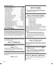
INTRODUCTION . . . . . . . . . . . . . . . . . . . . . . . . . . . 2
SPECIFICATIONS . . . . . . . . . . . . . . . . . . . . . . . . . . 2
FEATURES . . . . . . . . . . . . . . . . . . . . . . . . . . . . . . 2
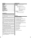
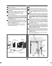
COMPONENT LOCATIONS . . . . . . . . . . . . . . . . . . . . . . 3
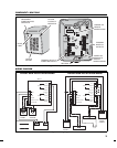
WIRING DIAGRAM . . . . . . . . . . . . . . . . . . . . . . . . . 3
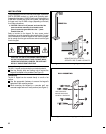
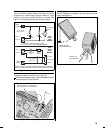
INSTALLATION . . . . . . . . . . . . . . . . . . . . . . . . . . . 4
FACTORY DEFAULTS . . . . . . . . . . . . . . . . . . . . . . . . . 6
BASIC PROGRAMMING . . . . . . . . . . . . . . . . . . . . . . . 6
PROGRAMMING OPTIONS . . . . . . . . . . . . . . . . . . . . . 7
AK-11 OPERATION . . . . . . . . . . . . . . . . . . . . . . . . 10
MANAGER’S ENTRY CODE LOG . . . . . . . . . . . . . . . . . . 11
LINEAR LIMITED WARRANTY . . . . . . . . . . . . . . . . . . . 12
FCC NOTICE . . . . . . . . . . . . . . . . . . . . . . . . . . . . 12
2