


Section 2: Installation
Settings and
Connections
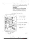
To connect the RCM8:
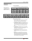
1. Set the SW1 DIP Switches as described in the tables below:
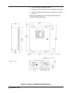
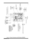
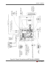
Refer to Figure 3 when
making physical connections
to the RCM8. Refer also to
Appendix B to define the
application you wish to install.
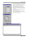
SW1 Switches 1 and 2—Address
Switch 1 2
RCM8 (Input #) OFF ON OFF ON
1 (1-8) X X
2 (9-16) X X
3 (17-24) X X
4 (25-32) X X
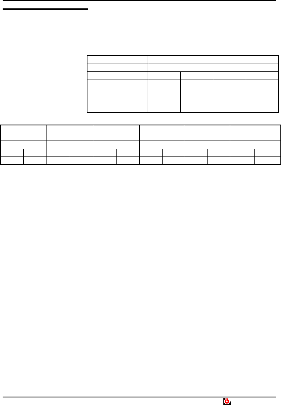
EIA-485
Master/Slave
EIA-485
Baud
Latching
Alarms
Repeater
Terminal
Baud Rate
Alarm Relay
(Silence/Reset)
3 4 5 6 7 8
OFF ON OFF ON OFF ON OFF ON OFF ON OFF ON
M S 9600 1200 OFF ON OFF ON 1200 2400 OFF ON
DIP Switch SW1 Descriptions
• Address (1 and 2)—Addressing allows up to four RCM8
units to be linked together. Overlapped addresses are
allowed only for dial-up operation without SiteScan.
• EIA-485 Master or Slave (3)—If ON, the Master unit polls
the EIA-485 Slaves and has dial-out capability for the
connected units. For Slave units at the ends of each EIA-485
string, set P4 jumper to IN. For all other units, set the P4
jumper to OUT. Modems do not directly attach to slave
units.
• EIA-485 Baud (4)—9600 baud works for most multiple-
unit applications. If communications are not working: check
cable distance; check for a noisy communications
environment; or try using 1200 baud.
• Latching Alarms (5)—When ON, alarms will not clear
until the Silence/Reset switch is pressed and held for two
seconds.
• Repeater (6)—A repeater RCM8 unit is connected at a
different location to echo alarms received by the primary
unit(s). When ON, the eight inputs of the repeater unit are
disabled and the display echoes incoming alarms. Master
repeaters display all alarms. Slave repeaters display alarms
only from RCM8 with a matching address.
Liebert RCM8 • 7