


DISASSEMBLY, REASSEMBLY, INSPECTION, AND MAINTENANCE 3-59
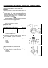
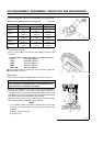
Balancer
•
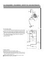
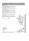
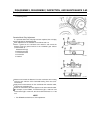
Using a micrometer, measure the balancer guide hole bore of the
balance weight in several places.
Balancer Guide Hole Bore Service Limit (maximum)
FE250, 290: 26.118 mm (1.0283 in)
FE350, 400: 26.097 mm (1.0274 in)
If the measured value is greater than the service limit, replace the
balance weight. On the FE350 and 400, the bushing can be replaced.
A: Guide Hole
B: Balance Weight
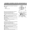
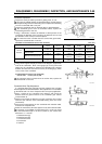
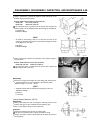
NOTE
To install a new bushing, drive it in so that the end face of the
bushing is flush with the end face of the balance weight as shown
in the diagram on the right.
A: Bushing
B: Balance Weight
•
Using a micrometer, measure the diameter of the balancer guide in
several places.
Balancer Guide Diameter Service Limit (minimum)
FE250, 290, 350, 400: 25.907 mm (1.0593 in)
If the measured value is smaller than the service limit, replace the
balancer guide with a new one.
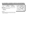
Reassembly
•
Make sure to apply fresh engine oil to the sliding and rotating areas.
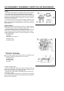
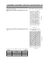
2. Install the balancer on the crankshaft in the following order:
Balance weight
link rod spacer
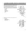
NOTE
Install the spacer with its chamfered end facing the link rod.
A Balancer Weight
B: Spacer
C: Link Rod
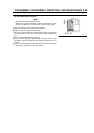
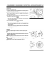
Uniaxial Rotation Balancer (FE170)
Disassembly
•
Remove the crankcase cover and align the matching marks on the
balance drive gear of the crankshaft and the balance gear.
•
Take out the balancer shaft from the crankcase.
Inspection
•
Inspect the balancer gear for wear or broken teeth.
If the gear is excessively worn, replace the balancer shaft.
•
Using a micrometer, measure the diameter of the balancer journal in
several places.