


3-58 DISASSEMBLY, REASSEMBLY, INSPECTION, AND MAINTENANCE
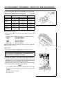
Balancer
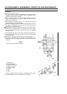
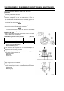
Reciprocal Movement Balancer (FE400, 350, 290, 250)
Disassembly
•
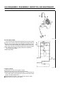
Remove the retaining nuts from the balancer guide and pull out the
balancer guide from the crankcase.
•
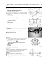
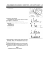
Remove the connecting rod bolt and remove the connecting rod cap.
•
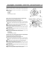
Turn the crankshaft to be near the top-dead-center to push the
connecting rod up. Then, turn the crankshaft 90
counterclockwise
as viewed from the PTO side. Remove the crankshaft (together with
the balancer) from the crankcase, through an area in which it does
not interfere with the connecting rod.
NOTE
Be careful not to damage the oil seal when removing the crankshaft.
•
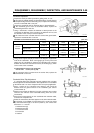
Remove the balancer link rod from the crankshaft.
NOTE
The balancer link rod on the PTO side cannot be disassembled
because the crankshaft gear is pressed in.
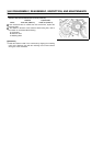
Inspection and Repair
•
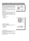
Using a micrometer, measure the bearing bore of the big and small
ends of the link rod in several places.
Link Rod Bearing Bore Service Limit (maximum) (Unit: mm)
Small End Bore Big End Bore
FE250 12.057 (0.4747 in) 47.106 (1.855 in)
FE290 12.064 (0.4750 in) 47.126 (1.855 in)
FE350, 400 12.057 (0.4747 in) 50.106 (1.973 in)
A: Link Rod Big End Bearing Bore
B: Small End Bearing Bore
If the measured value is greater than the service limit, replace the
link rod. On the FE290, the bushing can be replaced.
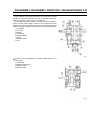
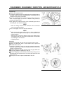
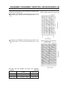
Replace the link rod bushing as follows:
•
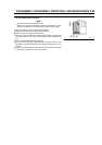
Support the big end of the link rod as described in the diagram, and
use a driver to pull the bushing out.
A: Bushing Driver
B: Bushing
C: Link Rod
D: Tool Base
•
Wash the disassembled parts and allow them to dry.
•
Apply engine oil to the new bushing.
•
Using a bushing driver, install the bushing so that the gap of the
bushing is positioned as shown in the diagram. Drive the bushing so
that it is 1mm deeper than the end face of the link rod.
A: Depression
B: Bushing Gap