


8 ASSEMB
LY
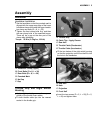
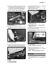
Left Switch Housing
•
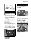
Connect the left switch housing connector to
the starter lock-out switch on the clutch lever
assembly.
A. Clutch Lever Assy
B. Starter Lock-out Switch
C. Connector
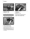
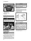
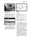
•
Fit the two halves of the left switch housing
together so that the small projection on the
front half fits into the hole in the handlebar.
A. Rear Half
B. Hole
C. Projection
D. Front Half
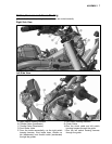
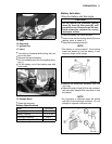
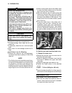
•
Insert the two screws (D = 5, L = 25) and
tighten them securely.
A. Left Switch Housing
B.Screws(D=5,L=25)
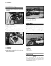
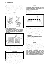
Clutch Cable
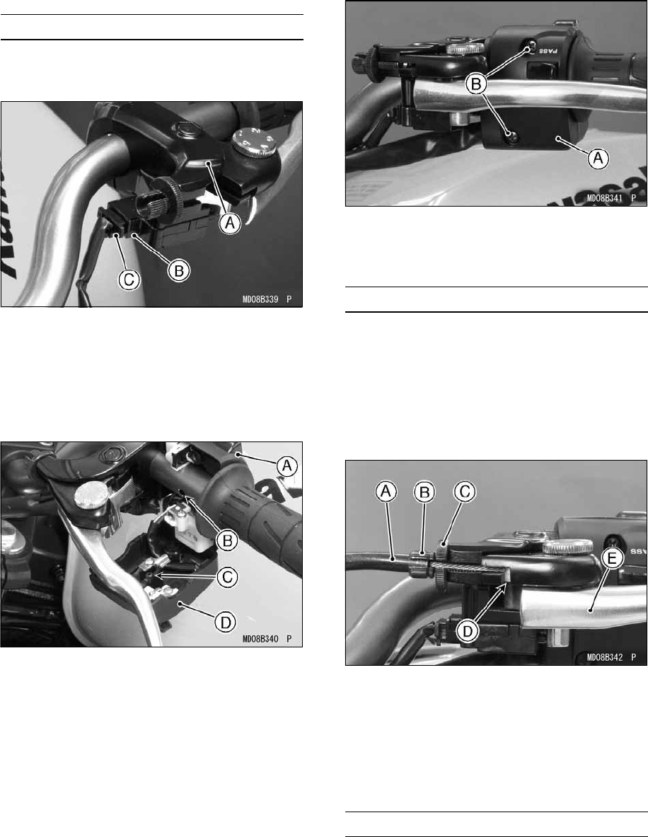
•
Apply a light coat of grease on the clutch inner
cable.
•
Line up the slots on the clutch lever, locknut,
and adjuster.
•
Fit the tip of the clutch inner cable into the
lever socket, slide the inner cable through the
slots, and release the outer cable into the ad-
juster.
A. Clutch Cable
B. Adjuster
C. Locknut
D. Cable Tip
E. Clutch Lever
Lower Fairing
NOTE
żIt is recommended that the lower fairing
should be installed after completing the steps
in the “Coolant” section on page 20 in the
PREPARATION chapter.