


Installation Instructions
OUO6050,0000A80 –19–05JUL07–2/3
PC9304 –UN–11AUG06
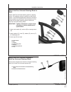
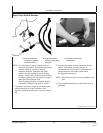
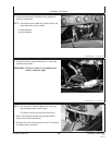
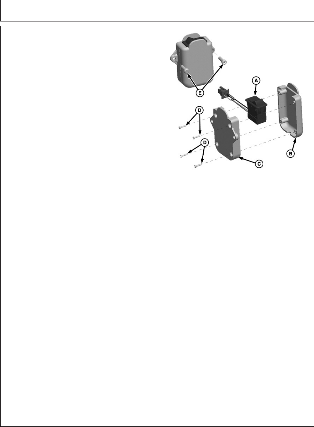
Auxiliary Resume Switch
A—Switch
B—Front Case
C—Rear Case
D—Screws that hold Case Together (4 Used)
E—Bolts that connect Case to Vehicle (2 Used)
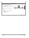
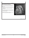
Switch Cover Direct Mounting:
1. Find a suitable location in the cab or operator’s station
for the assembly to be mounted that will be out of the
way of normal vehicle operation.
NOTE: Harnessing will also need to be routed so it does
not interfere with any vehicle functions performed
by the operator.
Use clips provided to secure harnesses.
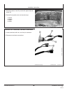
2. Mark and drill pilot holes using a 5mm (3/16’) drill bit
for each of the two mounting holes in the assembly.
IMPORTANT: Use caution when drilling into a panel
so that hidden wires or controls are not
damaged.
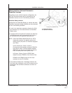
3. Attach the assembly using the screws provided and
ensure the assembly is rigid.
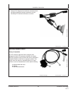
4. Connect the harness to the ATU harness at the 9-pin
round connector.
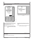
5. Test switch functionality using the ATU diagnostic
screens to ensure proper operation.
NOTE: The switch direction can be changed by
disassembling the plastic enclosure and flipping
the switch mount direction if necessary.
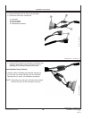
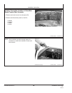
Panel Mounting:
1. Find a suitable panel mount location in the cab or
operator’s station for the switch that will be out of the
way of normal vehicle operation.
NOTE: Harnessing will also need to be routed so it does
not interfere with any vehicle functions performed
by the operator.
Use clips provided to secure harnesses.
2. Disassemble the switch from the plastic enclosure by
removing the (4) screws.
PC20864 (05JUL07) 18 Installation Instructions
070507
PN=20
Continued on next page