


03524832_ed13 3
Moisture will collect at the bottom of the receiver causing
corrosion and icing in cold weather. If either of these conditionsin cold weather. If either of these conditions
exist, the starter will not operate. After all connections have been
made, check each joint with a soap bubble test,
7. Installation of a “glad hand” for emergency repressurizing the
system is recommended. To keep the “glad hand” clean and free
of dirt, and to protect it from distortion, a second “glad hand”
closed by a pipe plug can be mated to it, or a glad hand protector
bracket can be used.
8. Whenever possible, always mount the starter so that the exhaust
port is downward This will help prevent any accumulation of
water in the starter motor.
9. For increased protection during extended shelf life, the motor
components of the starter have been coated with
Ingersoll Rand No. 50 Oil. This oil will be dispersed during the first
few cycles of the starter.
Relay Valve Location
Ingersoll-Rand recommends that the Relay Valve be mounted on the
air tank. As an alternate location, the Relay Valve can be mounted
on the starter. Mounting on the starter gives better control of the air
supply closer to the point of use and provides more starts per tank
of air. However, mounting on the starter adds overhung weight and
subjects the air supply lines to dynamic pressure at all times.
* Registered Trademark of Loctite Corporation
** Registered Trademark of Permabond Corporation
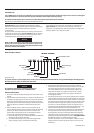
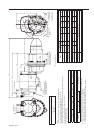
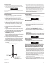
Orientation of the Air Starter
If the factory orientation will not t your engine due to radial location
of the Drive Housing or location of the inlet and/or exhaust ports,
re-orient the starter as follows:
1. Refer to the dimension illustration and note that the drive
housing can be located in anyone of eighteen radial positions
relative to the gear case. The exhaust port (motor housing) can
be located in any one of four radial positions relative to the Gear
Case, and the air inlet (Motor Housing Cover) can be located in
any one of four radial positions relative to the exhaust port.
2. Study the engine mounting requirements, and determine the
required orientation of the Drive Housing relative to the Gear
Case. If the Drive Housing has to be reoriented, remove the
twelve Drive Housing Cap Screws and rotate the Drive Housing to
its required position.
NOTICE
Do not separate the Drive Housing from the Gear Case Cover.
Reinstall the Drive Housing Cap Screws and tighten them to 100 in-lb
(11 Nm) of torque.
3. When orienting the Drive Housing relative to the Gear Case,
determine if the exhaust port will be at the bottom and if the
inlet port will be favorably located for hose installation. If either
or both of these members must be reoriented, remove the four
Motor Housing Cover Cap Screws, and rotate the Motor Housing
and/or Motor Housing Cover to its desired position.
NOTICE
Do not separate these members from each other or from the
Gear Case. Reinstall the Motor Housing Cover Cap Screws and
alternately tighten them to 25 ft-lb (34 Nm) of torque.
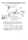
Mounting the Air Starter
1. Study the piping diagram Dwg. TPC585.
2. The air receiver tank for a starter installation must meet
SAE J10B specifications or conform to ASME specifications. It
must have a working pressure capability equal to or greater than
the maximum pressure at which the starter will be operated.
3. When connecting the starter to a receiver tank that is already in
service, bleed off the air pressure by opening the drain valve.
WARNING
Bleed o the air pressure through a valve or petcock. Do not
remove a plug from the tank while the tank is still pressurized.
Drain o any water that has accumulated in the bottom of the
tank.
4. Using a 1-1/4” short nipple, install the SRV125 Starter Relay Valve
on the end of the receiver tank as shown in the piping diagram.
NOTICE
Make certain the connection is made to the inlet side of the Relay
Valve indicated by the word ‘IN” cast on the valve body.
5. Install the No. SMB-618 Starter Control Valve on the dash panel
(for vehicular installations) or some other appropriate panel (for
stationary installations).
6. Attach No. TA-STR-100 Starter Instruction Label to the control
panel adjacent to the Starter Control Valve.
7. Mount the No. 150BMP-1064 Air Pressure Gauge on or adjacent
to the control panel. It should be located where it is readily visible
to the operator of the Control Valve.
8. Connect the Starter Control Valve to the Relay Valve with 1/4”
hose. Install a Tee in this line with a short feeder hose to the
Pressure Gauge.
NOTICE
Make certain the hose is connected to the “SUPPLY” side of the
Starter Control Valve.
9. To determine the exact length of 1-1/4” air hose required, run a
piece of heavy-duty hose or some other flexible tubing of the
same diameter from the Relay Valve on the receiver to the Starter
location on the engine.
10. Attach the 1-1/4” air hose to the outlet side of the Relay Valve, and
run the hose through the frame to its final position at the starter
location.
11. At this point, determine if it is feasible or practical to attach the
hose to the starter before or after the starter is actually mounted.
In many cases, it may be necessary to attach the hose to the
starter before mounting.
12. If possible, liberally grease the teeth on the ring gear with a
good, sticky gear grease or motorcycle chain lube. This will help
promote the life of the ring gear and the Starter Pinion.
13. Place the starter into position, and mount it on the flywheel bell
housing. Tighten the mounting bolts to 100 ft-lb (136 Nm) of
torque.
14. If the exhaust is not to be piped away, install a No. 150BM-A674
Muffler or No. 150BM-A735 Road Splash Deflector in the exhaust
port on the Motor Housing of the Starter.
15. Pressurize the complete starting system and check every
connection with a soap bubble test. There must be no leaks.
Barring Over the Engine
Occasionally, for setting injectors and/or for timing purposes, it may
be desirable to bar over the engine in such a manner that any given
piston can be stopped at any given location. This is very easily done
with a 150BMG Starter.