


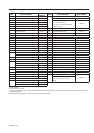


03524832_ed13 11
Inspection of Parts
1. Discard all O-rings and gaskets. These should not be reused.
2. Check all grease seals. If they appear worn or distorted, remove
them from their parent member and discard.
NOTICE
Discard any grease seal that was removed during disassembly
of the starter.
3. Check all needle bearings. Discard any needle bearing that was
pressed from a parent member during disassembly of the starter.
Remove and discard any other needle bearing that appears worn,
distorted, has loose needles or does not run freely.
4. Check all ball bearings. These should run freely without any rough
spots or binding. Discard any bearing that gives any indication
of wear. Check the Vanes for separation, chipping, wear, checks,
etc. See that they t freely in the vane slots in the Rotor. We
recommend that a complete new set of Vanes be installed
whenever the Starter is disassembled.
Assembly
General Instructions
1. Always press on the inner ring of a ball-type bearing when
installing the bearing on a shaft.
2. Always press on the outer ring of a ball-type bearing when
pressing the bearing into a bearing recess.
3. Whenever grasping a starter or part in a vise, always use
leather-covered or copper-covered vise jaws. Take extra care with
threaded parts or housings.
4. Always clean every part and wipe every part with a thin lm of
Ingersoll Rand No. 50 Oil before installation.
5. Check every bearing for roughness. If an open bearing must
be cleaned, wash it thoroughly in a clean, suitable, cleaning
solution and dry with a clean cloth. Sealed or shielded bearings
should never be cleaned. Work Ingersoll Rand No. 130 Grease
thoroughly into every open bearing before installation.
6. Apply a lm of o-ring lubricant to all o-rings before nal
assembly.
7. Lubricate all open bearing and gear teeth with a liberal coat of
Ingersoll Rand No. 130 Grease. Lubricate Starter Drive Housing
Bearing (30) and gear teeth with a liberal coat of Ingersoll Rand
No. 130 Grease. Work about 3 cc into the teeth of the Drive Gear.
8. Lubricate the Gear Case and Gear Case components with
Ingersoll Rand No. 130 Grease.
9. When assembling the motor always use new O-rings.
10. Before installing O-rings, coat liberally with O-ring lubricant. After
the O-ring is installed, coat the O-ring again with o-ring lubricant
and apply O-ring lubricant to O-ring grooves.
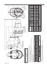
11. The Cylinder Dowel (12) maintains the alignment of the Motor
Housing Cover (1), Front End Plate (39), Cylinder (11) and Rear
End Plate (10). The end of the Dowel ts into a shallow hole in the
face of the Motor Housing Cover. It is important that the end of
the Dowel is in the hole and remains there during assembly.
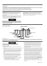
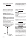
12. Unless otherwise noted, always press on the stamped end of a
needle bearing when installing the needle bearing in a recess.
Use a bearing inserting tool similar to the one shown in
Dwg. TPD786.
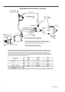
Needle Bearing inserting Tool
Shoulder to
Regulate Depth
Pilot to t I.D. of Bearing.
Length of Pilot to be
approximately 1/8” less than
length of Bearing
15°
(Dwg. TPD786)
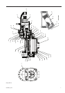
Assembly of Motor
1. Position the Rotor (40) vertically, splined end down.
2. Place the Rear End Plate (10), crescent grooved side rst, onto the
hub of the Rotor.
NOTICE
Make sure that all notches and ports are in alignment.
Refer to Dwg. TPA683-2.
3. Install the Rear Rotor Bearing (8) onto the hub of the Rotor until it
contacts the Rear End Plate. Make certain the End Plate does not
bind against the Rotor.
4. Install the Rear Rotor Bearing Retainer (9) in the groove on the
hub of the Rotor.
5. Grasp the Motor Housing Cover (1), motor bore face upward,
in copper-covered or leather-covered vise jaws. Swivel the vise
so that the air inlet is facing you. Cover the bore of the bearing
recess with a thin lm of Ingersoll Rand No. 130 Grease.
6. Check the nameplate on the Starter to determine whether you
have an “LH” model or “RH” model.
For “LH” models: While facing the air inlet on the Motor Housing
Cover, insert the Cylinder Dowel (12) in the dowel hole on the
right of the inlet.
For “RH” models: While facing the air inlet on the Motor Housing
Cover, insert the Cylinder Dowel (12) in the dowel hole on the left
of the inlet.
NOTICE
Make certain the Cylinder Dowel is installed in the proper dowel
hole. If you put it in the wrong dowel hole, the motor will rotate
in the wrong direction.
7. Place the Motor Housing Gasket (7) in the bore of the Motor
Housing Cover.
NOTICE
Make sure that the Motor Housing Gasket is installed with the
Cylinder Dowel hole positioned upward and properly oriented
relative to the Cylinder Dowel. The Cylinder Dowel hole in the
Gasket is the hole which is centered between the two angled
ports in the Gasket. Refer to Dwg. TPA683-2.
8. Place the assembled End Plate and Rotor into the Motor Housing
Cover that the Cylinder Dowel passes through the dowel hole in
the End Plate, and so that the air port in the End Plate aligns with
the port in the Gasket and Motor Housing Cover.
9. Place the Cylinder (11) down over the Rotor so that the Cylinder
Dowel passes through the dowel hole in the Cylinder and so that
the air port in the Cylinder is aligned with the air port in the Rear
End Plate, Gasket, and Motor Housing Cover.
10. Place the Motor Housing (14) down over the Cylinder making
certain that the prick punch marks on the Motor Housing Cover
and Motor Housing are aligned.
11. Liberally coat each Vane (13) with Ingersoll Rand No. 50 Oil and
insert a Vane into each slot in the Rotor. Make certain the straight
edge of each Vane faces the Cylinder.