


6 03524832_ed12
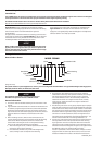
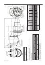
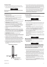
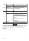
150BMG Series Air and Gas Starters Typical Installation
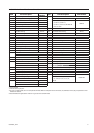
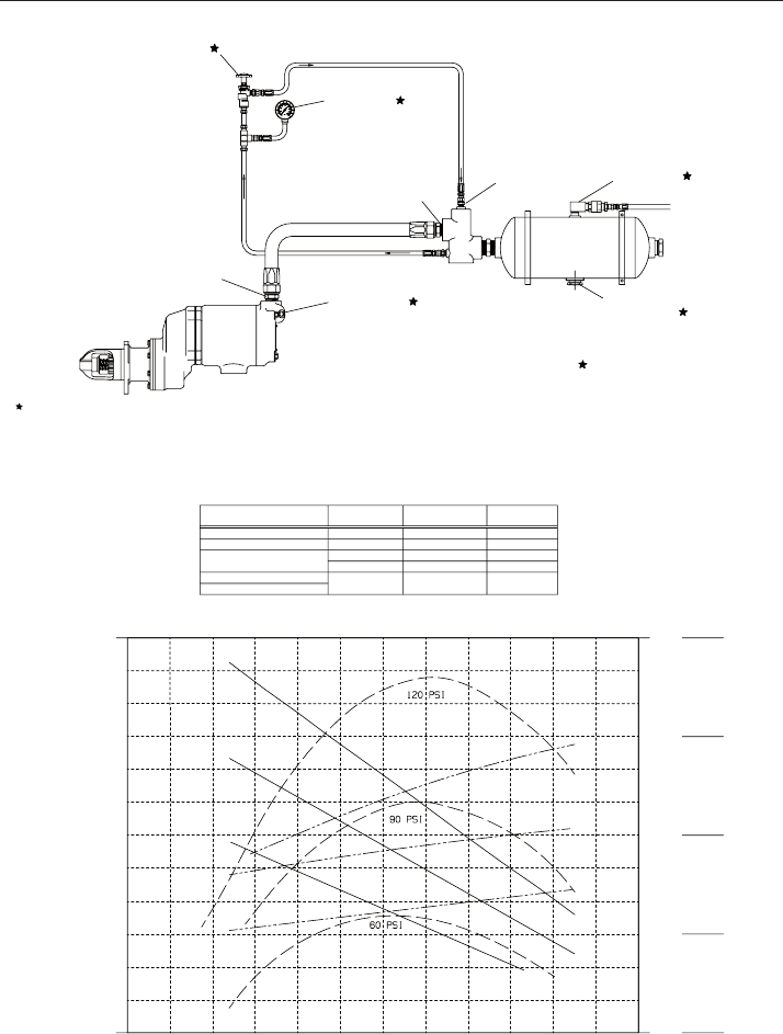
Torque (lb-ft)
Power (HP)
Flow (SCFM)
Series 150BM and 150BMG Performance Curves
0
20
40
60
80
100
120
25
20
15
10
300
600
900
1200
50
0 500
1000
1500
Speed (RPM)
2000 2500 3000
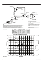
Starter
3BM, 5BM
0-30’ # 12 (3/4 “)
SRV 100
SRV 100
SRV 100
SRV 125
SRV 150
# 12 (3/4 “)
# 16 (1 “)
# 20 (1 1/4“)
# 24 (1 1/2“)
0-30’
0-10’
10-30’
0-50’
SS175
150BM/LF, SS350
SS810, 815, 825, 850
ST750, 799
Hose Length Hose Size
SRV Size
The performance of the Starter is dependent on the pressure at the inlet of the starter.
This pressure is eected by the pressure drop between the Air Receiver Tank and the Starter.
The most signicant pressure drops will occur in ttings (Valves, Tees, Elbows, etc.)
The next signicant source of pressure drop is the hose. The following table provides
recommended hose and Starter Relay Valves (SRV) sizes for typical one starter installations.
Systems with many ttings or long hose should be analyzed and sized individually.
For Gas Operation the exhaust outlet must be piped
away to a safe location.
For Natural Gas Operation, Piped Exhaust must be
used and Drive Housing vent plug replaced with
suitable hose which connects into piped exhaust
system.
For Air Applications a Muer or Splash Guard
Deector must be used.
Ingersoll Rand Part Number
Starter control Valve
SMB-G6618
Air Pressure Gage
150BMP-1064L
Check Valve
150BMP-1056
Drain Valve
150BMP-1067
1/2 NPT
# 4 Hose (1/4”)
# 4 Hose (1/4”)
# 4 Hose (1/4”)
JIC 37˚ Adapter
1 1/2 NPT
Air
Receiver
Tank
1 1/2” NPT
HDL3 Luricator
See Recommended
Hose Size
JIC 37˚ Adapter
1/4 NPT
Air Supply
Note:
Use Seleant on all pipe connections.
SMB-441
(Dwg. TPC585)
(Dwg. TPC611)