


12 03524832_ed12
12. Set the Front End Plate (39), crescent grooved side rst, onto the
Cylinder so that the Cylinder Dowel passes through the dowel
hole in the End Plate. Make sure that all notches and ports are in
alignment.
13. Install the Front Rotor Bearing (37) onto the splined shaft of the
Rotor until it seats against the Front End Plate. Do not bind the
End Plate against the Rotor.
14. Slide the Rotor Pinion (36) onto the rotor shaft.
15. Install the Rotor Pinion Retainer (35) in the groove on the rotor
shaft so that the concave side of the Retainer faces the Rotor
Pinion.
16. Apply a light coat of Ingersoll Rand No. 130 Grease to the Gear
Case Gasket (38) and place the Gasket in the motor bore of the
Gear Case.
17. Set the Gear Case on the assembled motor, making certain the
prick punch marks on the Gear Case are aligned with those on
the Motor Housing.
18. Turn the entire assembly over so that the Motor Housing Cover is
upward. Make sure that the Cylinder Dowel remains seated in the
shallow hole in the face of the Motor Housing Cover.
19. Install the Motor Housing Cover Cap Screws (5) and Lock Washers
(6). Tighten the Cap Screws alternately to 25 ft-lb (34 Nm) of
torque.
Assembly of Drive Gear
1. If the Drive Shaft Grease Seal (22) was removed from the Gear
Case Cover (21), press in a new Seal so that the inner lips of the
Seal face the bearing recess for the Drive Shaft Front Bearing (34).
2. Apply a thin lm of Ingersoll Rand No. 130 Grease to the Drive
Shaft (32) and the bore of the Drive Shaft Front Bearing, Drive
Shaft Collar (34), and Drive Gear (19).
3. Press the Drive Shaft Collar, beveled end rst, onto the keyway
end of the Drive Shaft until it seats against the shoulder of the
shaft.
4. Press the Drive Shaft Front Bearing onto the keyway end of the
Drive Shaft until it seats against the Drive Shaft Collar. Pack the
Bearing with Ingersoll Rand No. 130 Grease.
5. Install the Drive Gear Key (20) in the keyway on the Drive Shaft.
6. Press the Drive Gear (19), long hub rst, on the Drive Shaft until it
contacts the Drive Shaft Front Bearing.
Assembly of Gear Case
1. Set the assembled motor and Gear Case (15) on end with the
Gear Case upward.
2. Place the Bearing Ejecting Washer (16) in the bearing recess.
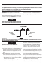
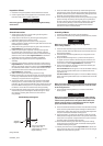
3. Using a needle bearing inserting tool, press the Drive Shaft
Rear Bearing (18), unstamped end rst, into the bearing recess
until the trailing face of the Bearing is ush with the face of the
bearing recess. Refer to Dwg. TPD786.
Work some Ingersoll Rand No. 130 Grease between the-rollers of
the Bearing.
4. Wipe a thin lm Ingersoll Rand No. 130 Grease on the Drive
Gear Thrust Washer (19A), and place the Washer on the lip of the
bearing recess in the Gear Case.
5. Apply about 8 ounces of Ingersoll Rand No. 130 Grease to the
assembled Drive Gear (19) and a uniform coat of
Ingersoll Rand No. 130 Grease to the Drive Shaft (32), making
certain to work the grease between all the gear teeth, splines and
bearing surfaces.
6. Insert the assembled Drive Gear and Shaft, short hub end rst,
into the Gear Case so that the short hub enters the Drive Rear
Bearing.
7. Slide the assembled Gear Case Cover, bearing recess rst, down
over the Drive Shaft until it seats against the Gear Case.
NOTICE
Check the inner lip of the Drive Shaft Grease Seal to make certain
that it did not fold outward toward the end of the Drive Shaft. If
it did fold outward, you must reinstall the Gear Case Cover using
a ne pointed instrument to roll the lip of the seal the proper
direction.
Assembly of Drive Housing
1. If the Drive Housing Bearing (30) was removed, stand the Drive
Housing (27) upright and press a new Drive Housing Bearing,
unstamped end rst, into the Drive Housing until the unstamped
end of the Bearing is ush with the inside face of the Drive
Housing boss. Work some Ingersoll Rand No. 130 Grease in the
Bearing.
NOTICE
Do not clean the Starter Drive (31) with solvent. If Starter Drive
appears dry, apply Ingersoll Rand No. 130 Grease to the threads
under the pinion.
2. Apply a thin lm of Ingersoll Rand No. 130 Grease to the surface
of the Drive Shaft (32).
3. Place the Starter Drive on the Drive Shaft.
4. Place the Drive Housing over the Drive onto the Gear Case Cover
(21). Rotate the Drive Housing into the required orientation as
indicated by the punch marks. At the same time, align the Cap
Screw holes in the Gear Case Cover and Housing.
5. Install the Drive Housing Cap Screws (23) and Lock Washers (24)
and tighten the Cap Screws to 100 in-lb (11 Nm) of torque.
Testing the Starter
1. Turn the pinion by hand in the direction of Starter rotation. The
pinion should advance smoothly and easily to the stop.
2. Turn the pinion opposite the direction of Starter rotation. The
gearing and motor should rotate freely with no binding.
3. Attach an air hose to the inlet and operate the motor slowly to
see that it functions properly and that the drive pinion rotates in
the proper direction. If the direction of rotation is incorrect, the
motor was improperly assembled.
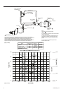
4. The chambers on the pinion teeth should be on the following
side of the teeth.