


Installation
313597E 9
Air and fluid hoses: Use only grounded
hoses with a maximum of 500 ft (150 m) com-
bined hose length to ensure grounding
continuity.
Air compressor: Follow manufacturer’s
recommendations.
Fluid supply container: Follow local code.
Solvent pails used when flushing: Follow
local code. Use only conductive metal pails,
placed on a grounded surface. Do not place
the pail on a nonconductive surface, such as
paper or cardboard, which interrupts ground-
ing continuity.
Suction device nozzle: Bond to metal con-
tainer from which it is suctioning by firm
metal-to-metal contact to a properly grounded
supply hose and pump.
Piping, valves, and fittings: Use only electri-
cally conductive materials. Bond and ground
per code.
Check your system electrical continuity after
the initial installation, and then set up a regular
schedule for checking continuity to be sure
proper grounding is maintained.
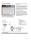
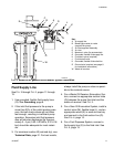
Air Line
Install the air line accessories as shown in
FIG. 3 through FIG. 5. Mount these accessories
on the wall or on a bracket. Be sure the air line
supplying the accessories is grounded.
1. Install an air regulator (C) and gauge to
control the fluid pressure. Locate it close to
the pump.
2. Locate a bleed-type master air valve (B)
close to the pump and use it to relieve
trapped air. Be sure the valve is easily
accessible from the pump and located
downstream from the regulator.
3. Locate another master air valve (E)
upstream from all air line accessories and
use it to isolate them during cleaning and
repair.
4. An air line filter (F) removes harmful dirt
and moisture from the compressed air
supply.
5. Install a grounded, flexible air hose (A)
between the accessories and the 1/2 npt(f)
pump air inlet (D). Use a minimum 3/8 in.
(10 mm) ID air hose.
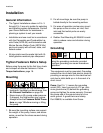
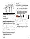
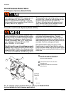
F
IG. 1. Ground screw and wire
GS R
ti12214a
Trapped air can cause the pump to cycle
unexpectedly, which could result in serious
injury from splashing.