


Installation
313597E 11
Fluid Supply Line
See FIG. 3 through FIG. 5, pages 11 through
13.
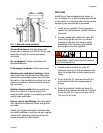
1. Use grounded, flexible fluid supply lines
(G). See Grounding, page 8.
2. If the inlet fluid pressure to the pump is
more than 25% of the outlet working pres-
sure, the ball check valves will not close
fast enough, resulting in inefficient pump
operation. Excessive inlet fluid pressure
also will shorten diaphragm life. Approxi-
mately 3 - 5 psi (0.02- 0.03 MPa, 0.21-0.34
bar) should be adequate for most materi-
als.
3. For maximum suction lift (wet and dry), see
Technical Data, page 21. For best results,
always install the pump as close as possi-
ble to the material source.
4. For a Waste Oil Receiver Evacuation Sys-
tem, connect an appropriate suction hose
(G) between the pump fluid inlet and the
waste oil receiver. See F
IG. 3.
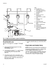
5. For a Gear Oil Evacuation System, install a
control valve (M), flexible hose (L), and an
appropriate wand (N) in each service bay
and connect to the fluid suction line (G).
See FIG. 4, page 12.
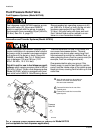
6. For a Fuel Dispense System, connect a
fluid supply line (G) to the fluid inlet. See
FIG. 5, page 13.
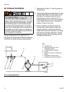
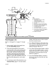
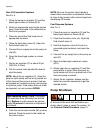
FIG. 3. Waste oil or general fluid transfer, typical installation
A
B
C
D
E
G
H
J
W
R
K
Key:
A Air supply line
B Bleed-type master air valve
(required for pump)
C Air filter/regulator assembly
D Air inlet
E Master air valve (for accessories)
G Grounded, flexible fluid supply line
H Fluid drain valve (required)
J Fluid shutoff valve
K Grounded, flexible fluid outlet line
R Ground wire (required, see page 8
for installation instructions)
W Waste oil receiver
ti14221b