


EXCEL 10 W7751H SMART VAV ACTUATOR
7 95-7553—04
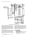
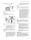
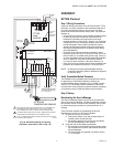
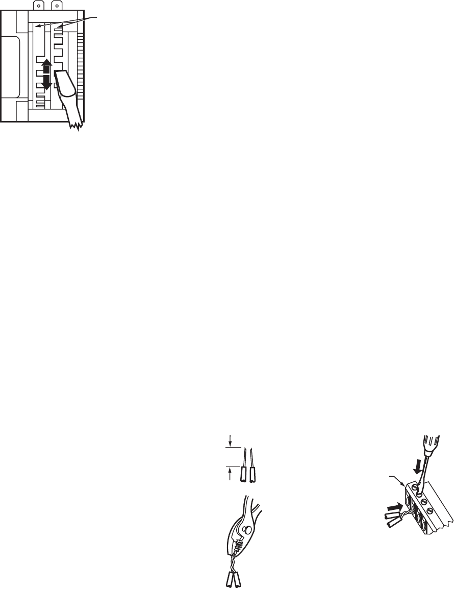
Fig. 14. Auxiliary switch cam adjustment.
NOTE: For 2 or 3 switch models, cams align with their
respective switches and are individually set
using the same procedure described above.
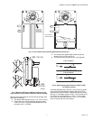
6. Ensure switch activation at the desired degree of stroke
by commanding the actuator to both fully open and fully
closed; see step 3.
NOTE: Switches can also be preset prior to actuator
installation if angular switch position is known.
Communications
Refer to LONWORKS® Bus Wiring Guidelines, form 74-8565,
for complete description of L
ONWORKS® Bus network topology
rules.f
If a longer L
ONWORKS® Bus network is required, a Q7740A
2-way or Q7740B 4-way Repeater can be added to extend
L
ONWORKS® Bus length, only if this is an Energy
Management (PAZX) Bus.
IMPORTANT
The Q7740A,B Repeaters cannot be used in
smoke control applications.
A Q7751A Router can only be added to an Energy
Management Bus to partition system into two segments
(effectively doubling L
ONWORKS® Bus length). Only one
router is allowed with each Excel 10 Zone Manager (or Excel
15 Building Manager), and each network segment can have a
maximum of one repeater.
Pull the cable to each device on the L
ONWORKS® Bus and
connect to communication terminals 11 and 12 (W7751H).
IMPORTANT
Screw type terminal blocks are designed to accept
no more than one 14 AWG (2.0 mm
2
) conductor.
Multiple 14 AWG (2.0 mm
2
) wires can be connected
with a wire nut. Include a pigtail with this wire group
and attach the pigtail to the individual terminal block.
Notes on LonWorks® Bus Communications Wiring:
• All field wiring must conform to local codes and ordinances
(or as specified on the installation drawings).
• Approved cable type is Level IV 22 AWG (0.34 mm
2
)
plenum or non-plenum rated unshielded, twisted pair, solid
conductor wire:
— For nonplenum areas, use CMP listed cable.
— In plenum areas, use CMP listed cable.
• Do not bundle output wires with sensor, digital input or
L
ONWORKS® Bus wires.
• Ensure that neither L
ONWORKS® Bus wire is grounded.
• In noisy (high EMI) environments, avoid wire runs parallel
to noisy power cables, motor control centers, or lines
containing lighting dimmer switches. Keep at least 3 in.
(76 mm) of separation between noisy lines and
L
ONWORKS® Bus cable.
• Do not use different wire types or gauges on the same
LONWORKS® Bus segment:
— Step changes in line impedance characteristics cause
unpredictable reflections on the L
ONWORKS® Bus.
Wiring Details
Wire to the terminal blocks as follows:
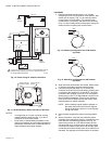
1. Strip 3/16 in. (5 mm) insulation from the conductor.
2. Insert the wire in the required terminal location and
tighten the screw to complete the termination.
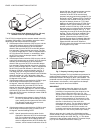
NOTE: With the exception of 14 AWG (2.0 mm
2
), if
inserting two or more wires into one terminal
location, twist wires together before inserting
them. See Fig. 15. Deviation from this rule can
result in improper electrical contact.
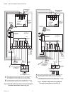
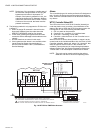
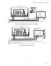
The controller on the W7751H has the terminal arrangement
shown in Fig. 16. Fig. 16 through 21 provide detailed wiring
diagrams for the W7751H. Refer to installation diagrams for
specific wiring.
NOTE: Ensure Configuration DIP Switch is set as shown in
Fig. 19. Switches 1 through 3 set ML7984B Valve
Actuator timing to match W7751H outputs (0.1 sec.
minimum with maximum time of 25.6 sec.). Switch 4
determines actuator action (Off = Direct Acting, On =
Reverse Acting).
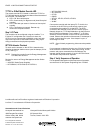
Fig. 15. Attaching two or more wires at terminal blocks.
SWITCH CAMS
M2076A
1/2
(13)
STRIP 1/2 IN.
(13 MM) FROM
WIRES TO BE
ATTACHED AT
ONE TERMINAL.
1.
2.
TWIST WIRES
TOGETHER
WITH PLIERS
(A MINIMUM OF
THREE TURNS).
3.
CUT TWISTED END OF WIRES TO
3/16 IN. (5 MM) BEFORE INSERTING
INTO TERMINAL AND TIGHTENING
SCREW. THEN PULL ON EACH WIRE
IN ALL TERMINALS TO CHECK FOR
GOOD MECHANICAL CONNECTION.
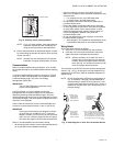
M11413
CONTROLLER OR
WALL MODULE
E-BUS CONNECTOR
TERMINALS