


EXCEL 10 W7751H SMART VAV ACTUATOR
95-7553—04 10
NOTE: During item 2, the occupancy override state of
the controller changes based on how long the
bypass/override button is depressed. For
example, if the button is pressed for 6 sec., the
node sends the Service Pin Message, AND the
node enters Continuous Unocc mode. To clear
Continuous Unocc mode, the button must be
pressed momentarily.
3. The following method is only supported on E-Vision and
L
ONSPEC™:
a. When an Assign ID command is issued from the
Honeywell Software listed, the node enters the
SERVICE_MESSAGE mode for five minutes.
b. In this mode, pressing the bypass/override button
causes the Service Message to be broadcast on the
network.
c. All other functions are normal in this mode.
d. If the bypass/override button is not available, short-
ing the controller Bypass Input terminals (on
W7751H short terminals 5 and 7) broadcasts the
Service Message.
Alarms
The commissioning tool is used to perform the ID Assignment
task. Once the ID Assignment and commissioning has been
done, check the controller status LED to determine if there are
any alarms.
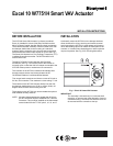
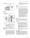
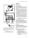
W7751 Controller Status LED
The LED on the front of a W7751H Controller (located just
under the plastic cover), provides a visual indication of the
status of the device. When the W7751H receives power, the
LED appears in one of the following allowable states:
1. Off—no power to the processor.
2. Continuous on—processor is in initialized state.
3. Slow blink—controlling, normal state.
4. Fast blink—when the Excel 10 VAV Controller has an
alarm condition.
When an Excel 10 has an alarm condition, it reports it to the
central node on the L
ONWORKS® Bus. Also, the Excel 10 VAV
Controller variables, AlarmLogX, where X is 1 through 5, that
store the last five alarms to occur in the controller, are
available. These points can be viewed through workstation
software. Refer to the VAV System Engineering Guide form,
74-2949 Table 12 for a description of the Excel 10 Alarms.
NOTE: The node can be reset by switching the node to
MANUAL and then to the normal operating mode.
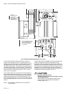
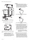
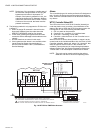
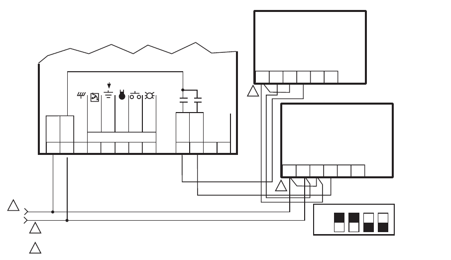
Fig. 19. W7751H to PWM Valve Actuator.
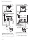
12345678 910
11
12
24 VAC
COM
OUT 1
OUT 2
E-BUS
24 VAC
W7751H
M10528
WALL MODULE
EARTH
GND
SENSOR
BYPASS
LED
NOT EARTH GROUND
TRIAC
EQUIVALENT
CIRCUIT
2
2
1
1
2
MAKE SURE ALL TRANSFORMER/POWER WIRING IS AS SHOWN;
REVERSING TERMINATIONS WILL RESULT IN EQUIPMENT MALFUNCTION.
TO ASSURE PROPER ELECTRICAL CONTACT, WIRES MUST
BE TWISTED TOGETHER BEFORE INSERTING INTO THE TERMINAL BLOCK.
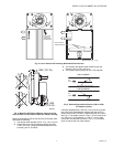
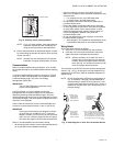
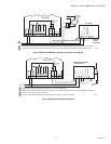
ML7984B
PERIPHERAL REHEAT
VALVE ACTUATOR
PWM OUTPUT
FROM CNTRL
PWM (H 24 VAC)
PWM VALVE ACTUATOR
24 (N)
24 (H)
T6 T5 C B W R
ML7984B
REHEAT VALVE
ACTUATOR
PWM OUTPUT
FROM CNTRL
PWM (H 24 VAC)
PWM VALVE ACTUATOR
24 (N)
24 (H)
T6 T5 C B W R
ON
OFF
1234
CONFIGURATION DIP SWITCHES
LOCATED ADJACENT TO THE INPUT
TERMINAL BLOCK ON ML7948B
SET PT