


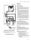
EXCEL 10 W7751H SMART VAV ACTUATOR
5 95-7553—04
IMPORTANT
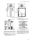
The minimum position set screw on the actuator is
not available on the W7751H device.
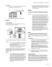
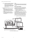
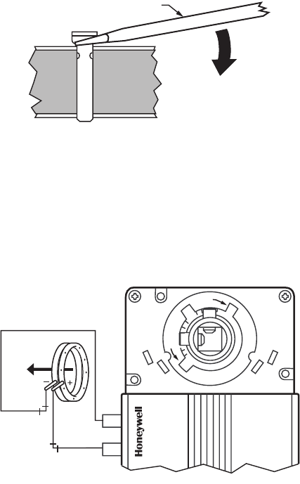
Fig. 8. Lifting a range stop pin out of its slot.
Piping
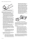
Air flow Pickup
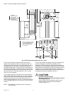
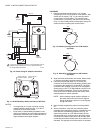
Connect the air flow pickup to the two connectors on the
controller of the W7751H. See Fig. 9.
Fig. 9. Smart VAV Actuator air flow pickup connections.
NOTES:
— Use 1/4 in. (6 mm) outside diameter with 0.040 in.
(1 mm) wall thickness plenum rated 1219 FR
(94V-2) pneumatic tubing.
— Always use a fresh cut on the end of the tubing
that connects to the air flow pickups and the
connectors on the VAV controllers.
Connect the high pressure or upstream tube to the plastic
restrictor labeled (+ HI) or P1 and the low pressure or
downstream tube to the restrictor labeled (- LO) or P2. See
labeling in Fig. 9.
NOTES:
— If controllers are mounted in unusually dusty or
dirty environments, a 5-micron disposable air filter
is recommended for the high pressure line
(marked as +) connected to the air flow pickup.
— When using twin tubing from pickup, split pickup
tubing a short length to accommodate connections.
— Tubing from air flow pickup to VAV controller
should not exceed three feet (0.914m). Lengths
longer than this can degrade flow sensing
accuracy.
— To prevent VAV air flow connector breakage, use
caution when removing tubing from it. Always pull
straight away from connector; never remove by
pulling at an angle.
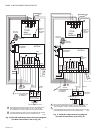
Wiring
All wiring must comply with applicable electrical codes and
ordinances, or as specified on installation wiring diagrams.
NOTES:
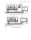
— For multiple controllers operating from a single
transformer, the same side of the transformer
secondary must be connected to the same input
terminal in each controller and the ground
terminals (3 on the W7751H, 28 on the W7751B,
and 32 on the W7751D,F) must be connected to a
verified earth ground for each controller in the
group. See Fig. 10. (Controller configurations are
not necessarily limited to three devices, but the
total power draw including accessories cannot
exceed 100 VA when powered by the same
transformer. See System Engineering form
74-2949 for power wiring recommendations.)
— All loads on an Excel 10 Controller must be
powered by a single transformer.
— Keep the earth ground connection (terminal 3)
wire run as short as possible. Refer to Fig. 16.
—Do not connect the analog ground terminal (5) to
earth ground. Refer to Fig. 16.
Power
The 24 Vac power from an energy limited Class II Power
Source must be provided to each Smart VAV Actuator. To
conform to Class II restrictions, transformers must not be
larger than 100 VA. The maximum current draw at 24 Vac is
1.25A.
IMPORTANT
— Power must be off prior to connecting to or removing
connections from output terminals 9 and 10.
— Use the heaviest gauge wire available, up to
14 AWG (2.0 mm
2
) with a minimum of 18 AWG
(1.0 mm
2
), for all power and earth ground wiring. For
nonplenum, open areas, run cables exposed (or in
conduit, if required).
— If the W7751H Smart VAV Actuator is used on
Heating and Cooling Equipment (UL 1995, US
only) and the transformer primary power is more
than 150 volts, connect the transformer secondary to
earth ground, see Fig. 10.
NOTE: Maintain a three-inch (76 millimeter) separation
between Triac outputs and L
ONWORKS® Bus wiring
throughout installation.
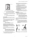
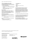
Auxiliary Switches
The 201052A,B,C Auxiliary Switch can be used with the
W7751H. It allows for control of equipment external to the
actuator (for example, electric reheat coils or fan) at an
adjustable point in the stroke (from 0 to 90 degrees) of the
actuator. The 201052 Switch is field-added. Self-tapping
Phillips head screws are included with the switch. The switch
can be mounted only one way (see Fig. 11) with the switch
contacts pointed to the top of the actuator.
SCREWDRIVER
M2065
AIRFLOW
DP PICKUP
AIRFLOW
DIRECTION
M10003
– LO
+ HI
CCW
CCW
CW
CW
60
45
45
60