


V4055A,B,D,E ON-OFF FLUID POWER GAS VALVE ACTUATOR
5 60-2309—13
IMPORTANT
1. All wiring must comply with all applicable electrical
codes, ordinances, and regulations. All wiring must
be NEC Class 1.
2. Voltage and frequency of the power supply connected
to this control must agree with those marked on the
device.
3. Loads connected to the Auxiliary Switch and/or Proof-
of-Closure Switch, if used, must not exceed the rat-
ings given in the Specifications section.
Install Valve
The actuator is mounted directly on the valve bonnet after the
valve is installed in the gas supply line. Refer to the instructions
packed with the gas valve for installation details. When
installing the gas valve, make sure:
1. Sufficient clearance is left to install and service the actuator.
2. Ambient temperatures at the valve location do not
exceed actuator ratings. See Specifications section.
3. Position of the valve permits hookup to the damper if one
is controlled.
Install Accessory Switches (If
Needed)
An spdt switch can be installed to operate an auxiliary load up
to 1/2 hp (0.37 kW). See Table 5. The switch can be adjusted
to operate at any point in the valve stroke.
A Proof-of-Closure Switch can also be installed with a V5055/
V5097C or E Valve (with double seal) on any V4055 Actuator
to provide a valve seal overtravel interlock. The spdt
Proof-of-Closure Switch is installed to make or break a circuit
when the valve is in the closed position. The switch is not
adjustable.
NOTE: Mark the actuator or valve to indicate any changes
made.
To install the switches:
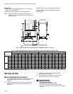
1. Remove the actuator faceplate (two screws).
2. Remove the silver-colored barrier to expose the actuator
stem.
3. Insert the Auxiliary Switch in the position indicated in Fig.
2. Fasten with two screws through the actuator base.
4. Insert the Proof-of-Closure Switch in the position shown
in Fig. 2. The switch mounts against the side of the
actuator housing. The mounting holes are spaced to
assure mounting the switch in the correct position.
Fasten with two screws through the actuator base. (The
Proof-of-Closure Switch is not adjustable.)
5. If only one switch is used, install the narrow barrier
included with the switch in the unused space.
6. Mount the actuator before making wiring connections
and adjustments to the Auxiliary Switch.
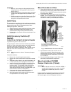
Mount Actuator on Valve
1. Check the final position of the valve body to be sure that
the actuator is in the proper position when mounted on
the valve. This is especially important when the actuator
is used to drive a damper.
2. If two smaller sized valves are mounted very closely
together, as in an Industrial Risk Insurers approved type
of valve train, it may be necessary to mount the
actuators off center to provide adequate clearance.
Fig. 2. V4055 Actuator with cover removed.
3. Slip the bottom collar of the actuator over the
valve bonnet assembly. Rotate the actuator to the
desired position and use a 5/32 in. Allen wrench to
securely tighten the two setscrews to 50 to 60 lb-in.
(5.7 to 6.8 N•m).
4. Connect the damper linkage, if used. Refer to the
instructions packed with the damper arm.
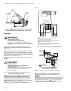
Mount and Adjust 7616BR
Damper Crank Arm (If Used)
IMPORTANT
When a damper crank arm is used with a NEMA 4
actuator that is exposed to ice or sleet, a suitable
shield must be installed to prevent ice or sleet
buildup.
Follow installation and adjustment directions included with
damper crank arm. Maximum pushrod travel is 2-5/16 in.
(59 mm) through a stroke of 52 degrees. See Fig. 3.
133568
AUXILIARY
SWITCH
133569
VALVE-
CLOSED
INDICATION
SWITCH
EACH SWITCH SECURED BY
TWO SCREWS FROM UNDERSIDE OF BASE.
ADJUSTING
SCREW FOR
AUXILIARY
SWITCH
IF ONLY ONE SWITCH IS USED, INSTALL BARRIER
IN OPEN POSITION.
M7326B