


V4055A,B,D,E ON-OFF FLUID POWER GAS VALVE ACTUATOR
60-2309—13 4
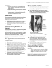
Accessories:
133568 Auxiliary Switch Bag Assembly (not for models with
maximum flow limit switch).
133569 Valve-Closed Indication Switch Bag Assembly.
NOTE: Check local codes for acceptance of adding the
switch and using the valve seal overtravel V5055C or
V5055E valves.
7616BR Damper Crank Arm (damper arm and clip).
Available Models: V4055 with NEMA 4 enclosure
(weatherproof).
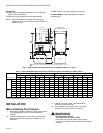
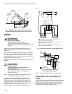
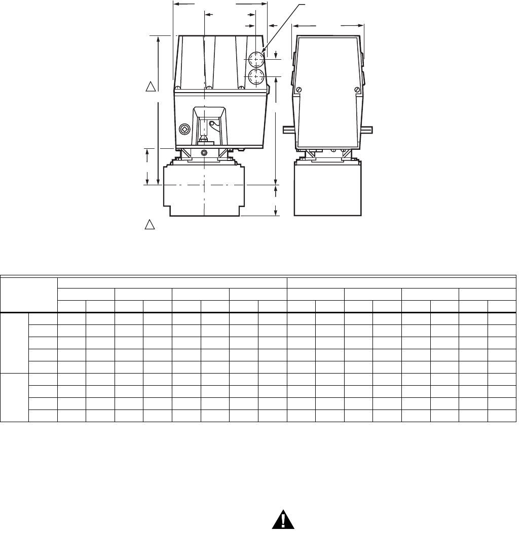
Fig. 1. Approximate mounting dimensions of V4055 Actuators in in. (mm).
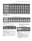
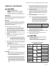
Table 7. Approximate Mounting Dimensions of V4055 Actuators with V5055 and V5097 Valves.
a
Valve size using accessory pipe adapter fitting.
INSTALLATION
When Installing This Product...
1. Read these instructions carefully. Failure to follow them
could damage the product or cause a hazardous
condition.
2. Check the ratings given in the instructions and on the
product to make sure the product is suitable for your
application.
3. Installer must be a trained, experienced flame
safeguard control technician.
4. After installation is complete, check out product
operation as provided in these instructions.
WARNING
Electrical Shock Hazard.
Can cause serious injury or death.
Disconnect power supply before making wiring
connections to prevent electrical shock and equipment
damage.
Valve Size
a
(in.)
V5055 V5097
Dim. A Dim. B Dim. C Dim. D Dim. A Dim. B Dim. C Dim. D
in. mm in. mm in. mm in. mm in. mm in. mm in. mm in. mm
Small
Body
3/4 11-1/8 283 2-3/4 70 8-3/16 208 5-3/4 146 11-1/8 283 2-3/4 70 8-3/16 208 2-1/2 64
1 11-1/8 283 2-3/4 70 8-3/16 208 5-3/4 146 11-1/8 283 2-3/4 70 8-3/16 208 2-/12 64
1-1/4 11-1/8 283 2-3/4 70 8-3/16 208 5-3/4 146 11-1/8 283 2-3/4 70 8-3/16 208 2-1/2 64
1-1/2 11-1/8 283 2-3/4 70 8-3/16 208 5-3/4 146 11-1/8 283 2-3/4 70 8-3/16 208 2-1/2 64
2 11-1/8 286 2-7/8 73 8-5/16 211 8-3/8 213 11-3/4 298 3-3/8 86 8-3/8 213 4 102
Large
Body
2 11-3/4 298 3-3/8 86 8-13/16 224 9-1/4 235 1-3/4 298 3-3/8 86 8-3/8 213 4 102
2-1/2 11-3/4 298 3-3/8 86 8-13/16 224 9-1/4 235 11-3/4 298 3-3/8 86 8-3/8 213 4 102
3 11-3/4 298 3-3/8 86 8-13/16 224 9-1/4 235 11-3/4 298 3-3/8 86 8-3/8 213 4 102
4 14-1/8 359 5-13/16 148 11-7/32 285 12-1/2 318 — — — — — — — —
D
A
1
1
(33)
KNOCKOUT FOR
1/2 INCH CONDUIT (4)
5 (127)
1-9/32
27/32 (21)
3-23/32 (95)
6-3/4 (172)
C
B
ALLOW 4 INCH (102 MM) CLEARANCE FOR ACTUATOR REMOVAL. M17755A
VALVE
VALVE