


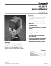

ML6874
OPERATION AND CHECKOUT
Operation and checkout
Operation:
The recommended valve actuator power source is a class
2, 24V transformer or 28Vdc across terminals T5 &T6.
Internal circuitry provides dc power for the electronic
sensing and drive motor circuits.
The motor is controlled by a microprocessor. Connecting
B to R tells the microprocessor to cause the actuator to
drive open, i.e. UP, in the Direct Acting Mode.
Connecting W & R will cause the actuator to drive closed,
i.e. DOWN, in the Direct Acting Mode. For "floating"
control, if R remains open, the actuator will remain in the
last position. The DIP switches are scanned only on power
up, and tell the microprocessor if Direct or Reverse mode
is desired. Changes in the DIP switch setting will only
take effect if the power is off while the change is made.
At the end of the valve stroke, the actuator will develop
the necessary force for positive valve close-off. As forces
are developed, the current to the motor increases. The
microprocessor stops the actuator automatically when the
motor current, and forces reach the predetermined level.
!
CAUTION:
1. Disconnect power supply before beginning installation
to prevent electrical shock and equipment damage.
2. All wiring must comply with applicable local electrical
codes, ordinances and regulations.
3. Make certain that the voltage and frequency of the
power supply correspond to the rating of the device.
4. DO NOT connect 24 Vac between any signal input
terminals.
5. DO NOT electrically operate the ML6874 before
assembly to the valve because damage not apparent
to the installer may occur.
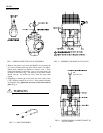
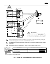
GENERAL NOTE:
1. For correct valve operation, the ML6874 must be field
configured with the DIP switches which are located
beside the terminal block, see wiring diagrams for
details. Turn power off before setting the DIP
switches .
2. There is a short delay in actuator response upon every
signal change. It is to screen any unwanted incoming
signals.
3. For proper operation, voltage on the T5 & T6 must not
be less than 22Vac or 24Vdc during running or force
generating stages.
REPLACEMENT NOTE:
1. The old ML684 actuators cannot be used with new
ML6874 valve actuators in the same circuitry, unless they
are isolated by an isolation relay to prevent cross-talking.
2. The ML6874 is a direct replacement for the old
ML684A1025 (160 lbs) in single actuator hook-up,
except when replacing the old reverse acting models, the
signal input wires to the new devices are no longer
needed to be reversed. Just set the DIP switch as shown in
Fig.7.
3. DO NOT replace the ML684A1009 (80 lbs ) with this
new ML6874 on the V5045 valve.
Checkout:( see General & Replacement Note )
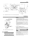
1. Make sure the valve stem is completely screwed into the
actuator drive shaft with no threads showing.
2. Make sure the valve stem is locked in place with the set
screw.
3. Check DIP switches for proper setting for Direct or
Reverse Acting mode.
4. Connect R & B. Valves stem should move up, in Direct
Acting mode.
5. Connect R & W. Valves stem should move down, in
Direct Acting mode.
6. For Floating operation, open R connection. Valve stem
should remain in position.
7. Operate the system ( valve, actuator and controller ) for
several cycles to ensure proper installation.
8. When checkout is complete, return the controller to the
desired setting.
Home and Building Control
Honeywell Limited/Limitee
Home and Building Control
Honeywell Inc.
Helping You Control Your World
155 Gordon Baker Road 1985 Douglas Drive North
North York , ON Golden Valley, MN 55422
Canada M2H 3N7 www.honeywell.com/building/components