


ML6874
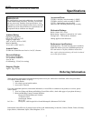
SPECIFICATIONS •INSTALLATION
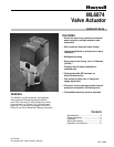
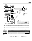
FIG. 1 -- DIMENSIONS OF ML6874 VALVE ACTUATOR IN MM (INCHES).
Installation
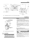
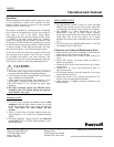
FIG.2 -- MINIMUM MOUNTING CLEARANCE.
!
CAUTION
1. Installer must be a trained service technician.
2. DO NOT electrically operate the ML6874
before assembly to the valve because damage
not apparent to the installer may occur.
Mounting:
1. Ensure that the valve body is installed correctly, that is, the
arrow points in the direction of the flow.
2. Although the actuator can be mounted in any position, it is
preferable that the ML6874 is mounted above the valve
body. This will minimize the risk of damage to the
ML6874 in the event of condensation or a valve gland
leak.
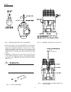
3. Remove the stem button (Fig. 3) from the valve stem. Save
the set screw inside the stem button for later installation.
The button itself is not needed.
4. Slide the position indicator (plastic disk or rubber O-ring)
over the valve stem. (See inset, Fig. 3) Indicator will self-
align to the marking on the yoke after one complete
operating cycle.
Assembly of ML6874 to the valve:
1. The drive shaft of the ML6874 has a threaded hole to link
with the valve stem. Slide the yoke over the valve bonnet
(Fig. 4)
2. Thread the ML6874 drive shaft onto the valve stem all the
way, until it is completely attached (with no threads
showing), by turning the valve actuator in a clockwise
direction, as viewed from above (depending on the valve
models, use a pin or wrench to keep valve stem from
turning). Note that the valve actuator is shipped with drive
shaft in the mid-position.
3. Care should be exercised when using tools on the valve
stem during tightening. (Fig.4) DO NOT damage the
threads or other parts of the stem.
4. Orient the conduit hole to the most desirable direction, then
tighten the LOCKNUTS on the U-bolt.
3