


ML6874
INSTALLATION
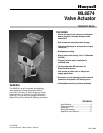
FIG.3 -- PREPARATION FOR VALVE ASSEMBLY.
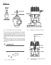
5. Remove the plastic cover from the ML6874 by loosening the
two screws located on the top (Note: These screws are captive.
Rotate three complete revolutions to remove cover ). Drop
either Slot Headed or Allen Hex type of set screw (both are
included in the plastic bag ) into the top of the shaft, slotted/
Hexed side up. Or use the set screw from the valve stem
button.
6. Depending on which type of set screw was used, with a 5 mm
(3/16") Slotted screwdriver or 1/8"x 6" Allen wrench (included
in the plastic bag), tighten the set screw to lock valve stem in
place (Fig. 6).
!
WARNING
g
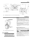
FIG. 5 -- U-BOLT ASSEMBLY.
4
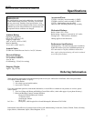
FIG. 4 -- ASSEMBLY OF ML6874A TO VALVE.
OR
Allen Wrench
FIG. 6. -- LOCKING ML6874A DRIVE SHAFT TO
VALVE STEM