


ML6874
WIRING
3
SPDT
Controller
2
ML6874
28 Vdc
OR
+
T6
T5
24 Vac
1
L1
L2
T5
T6
W
R
B
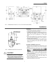
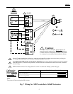
Caution:
In multiple actuators connection, power supply to all
actuators must be connected in a TRUE parallel fashion
to reduce excessive voltage drop. DO NOT "daisy chain"
i.e. connected to one actutator then branched to another.
!
ML6874
2
W
B
R
W
B
R
T5
T6
W
R
B
3
1
2
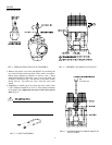
Allow 0.5 amps maximum for each device. Actuators and controller can share same transformer providing the
VA rating of the transformer is not exceeded and proper phasing is observed.
Use configuration DIP switches to select device functions: Direct acting function (actuator stem moves upwards
with R & B closed ) or Reverse acting function ( actuator stem moves downwards with R & B closed ). DO NOT
reverse wiring.
SPDT controller can be a low voltage Series 20 "on-off " or Series 60 "floating" (center-off) type.
Configuration
FUNCTION
DIP switches
located adjacent
Direct Acting Mode
to the input
terminal block
Reverse Acting Mode
NOTE:
Turn power off before setting the DIP switches.
DIP SWITCH CONFIGURATION
on
off
1 2 3 4
on
off
1 2 3 4
Fig. 7 Wiring for SPDT controller to ML6874 actuators
5