


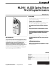

ML6195, ML6295 SPRING RETURN DIRECT COUPLED ACTUATORS
63-2537—1
7
Auxiliary Switches (ML6295C only)
The ML6295C models have line voltage, fully adjustable
auxiliary switches. The switch setting interval (or differential) is
5°.
The switches are set as follows:
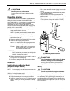
1. If the power is on, turn it off; the actuator will spring
return to the 0° position.
IMPORTANT
If the shaft coupling has been adjusted according to
the Range Stop Adjustment instructions, the position
indicator must also be adjusted to indicate 0 at the
fail-safe position. If this is not done, the position
indicator will not correspond to the auxiliary switch
adjustment settings, as shown on the label.
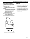
2. Use a flat blade screwdriver to turn the switch
adjustment dials to the desired settings.
NOTE: The numerical indication on the dials corresonds to
the location of the shaft coupling at which a signal
will be given by the switch (see Fig. 9).
Once power is restored, the actuator will return to normal
automated control.
Fig. 9. Actuator rotary range and auxiliiary switch
signal locations.
20
30
30
10
20
40
40
50
60
70
70
80
90
A
B
AUX
SWITCH
ADD
0°-5° 10° 20° 30° 60° 70° 80° 90°
0° 10° 20° 30° 60° 70° 80° 90°
M11699
CHECKOUT
To perform a checkout of the ML6195/ML6295 DCA, proceed
as follows:
1. Check the damper or valve position and make sure that
24 Vac is present on the red and black leadwires.
2. Connect 24 Vac to the appropriate leadwires (red to
violet or red to orange) to move the damper or valve to
the opposite position. The ML6195/ML6295 should
drive the damper or valve.
3. If the actuator does not run, verify that the actuator is
properly installed for either cw or ccw rotation.
4. If the actuator operates in the opposite direction than
desired, reverse the violet and orange leadwires.
5. If the actuator is correctly installed and still does not
run, replace the actuator.