


ML6195, ML6295 SPRING RETURN DIRECT COUPLED ACTUATORS
63-2537—1
4
CAUTION
Deteriorating vapors and acid fumes
can damage the actuator.
Install actuator in areas free of acid fumes and other
deteriorating vapors that can attack the metal parts of
the actuator.
Location
Install the actuator in a location that allows enough clearance
for mounting accessories and for servicing.
Refer to Warnings and Cautions (above) for locations to avoid.
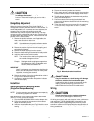
Mounting
The ML6195/ML6295 DCA has a self-centering shaft coupling
to accommodate specific shaft lengths, sizes, and shapes.
Proper actuator location and means of actuator rotation preven-
tion are necessary to avoid excessive strain on the output gear.
The ML6195/ML6295 DCA operates a damper or hydronic
valve by driving the shaft either cw or ccw, depending on the
design. All actuators are shipped with a 5° preload on the
spring. When power is applied to the actuator, the preload is
released and the actuator spring-returns 5° for tight closeoff.
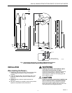
The ML6195/ML6295 DCA is designed for single-point
mounting. Single-point mounting is typically used when the
actuator is mounted on a damper frame. A mounting bracket
(see Fig. 1) is provided for installing the actuator.
CAUTION
Avoid damage to the damper or actuator.
Do not allow the mounting bracket to bind or clamp
the actuator to the duct.
Use the mounting bracket only to prevent the actuator
housing from rotating.
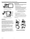
Preparation
Before installing the ML6195/ML6295 on the shaft, determine
the opening direction of the damper or valve for correct spring
return rotation and wiring connections. The ML6195/ML6295
can be mounted to provide clockwise or counterclockwise
spring return.
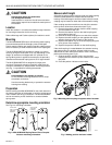
Determine appropriate mounting orientation
See Fig. 2 for mounting orientation.
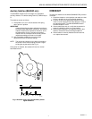
Measure shaft length
If the shaft is less than three inches in length, the shaft coupling
must be located between the damper/valve and actuator
housing. If the shaft length is more than three inches, the shaft
coupling may be located on either side of the actuator housing.
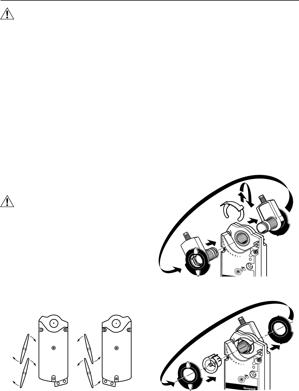
If the coupling must be moved from one side of the actuator
to the reverse, follow these instructions (see Fig. 3):
1. Remove the position indicator from the shaft coupling
and set it aside for later use.
2. Remove the retainer clip from the shaft coupling and
set it aside for later use.
3. Remove the shaft coupling from one side of the actuator.
4. Replace the shaft coupling on the opposite side of the
actuator aligning it with the mark on the housing.
5. Replace the retainer clip on the shaft coupling using the
inner groove of the coupling.
6. Replace the position indicator on the shaft coupling.
If the shaft coupling is located between the actuator housing
and damper/valve, the position indicator holder must be
attached to the other side of the actuator. If this is necessary,
perform the following (see Fig 4):
1. Slide the position indicator holder onto the shaft
coupling near the retainer clip and rotate it until it snaps
into place.
2. Place the position indicator on the holder.
CW TO OPEN
CCW TO CLOSE
(FAIL-SAFE
POSITION)
CW TO CLOSE
(FAIL-SAFE
POSITION)
CCW TO OPEN
M12443
Fig. 2. ML6195/ML6295 Spring Return Direct Coupled
Actuator mounting orientation.
Fig. 3. Mounting shaft coupling to opposite side of actuator.
M12441
Fig. 4. Adding position indicator holder.
M12440