


ML6195, ML6295 SPRING RETURN DIRECT COUPLED ACTUATORS
63-2537—1
5
CAUTION
Manually turning the shaft coupling
can damage the actuator.
Never turn motor shaft coupling by hand or with a
wrench.
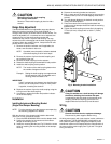
Range Stop Adjustment
The ML6195/ML6295 has an adjustable range stop feature.
When the rotational mounting of the shaft coupling is
changed, the actuator drives less than the full 95° stroke. The
stroke is adjustable in 5° increments and once adjusted, the
actuator drives until the shaft coupling reaches the
mechanical stop, which is a part of the housing. The stop
causes the motor to disengage and the shaft coupling drives
no farther. When the actuator returns, it stops at the fail-safe
position which is set as follows:
1. Remove the position indicator; and if applicable, the
holder, and set aside for later use.
NOTE: If possible, leave the position indicator attached
to the shaft coupling to aid in future steps.
2. Remove the retainer clip from the shaft coupling and
set it aside for later use.
3. Remove the shaft coupling from the actuator.
4. Rotate the shaft coupling to the desired fail-safe position.
5. Install the shaft coupling at this position.
NOTE: The location of the shaft coupling determines
the number of degrees of travel.
Example: Setting the shaft coupling at an approximate
fail-safe position of 20° (as indicated on the
housing), limits the stroke to 70°.
IMPORTANT
If the 5
°
preload was not released, see the Mounting
section, the fail-safe position moves 5
°
when power
is applied, increasing the stroke 5
°
.
6. Replace the retainer clip on the shaft coupling using the
inner groove of the shaft coupling.
7. If necessary, replace the holder and position indicator
on the shaft coupling.
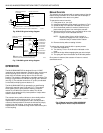
Installation
Installing Actuator and Mounting Bracket
(Single Point Damper Mounting)
NOTE: For valve mounting, see the literature accompanying
the mounting equipment or bracket.
With the direction of the damper shaft rotation determined
(either cw or ccw), proceed as follows:
1. Place the ML6195/ML6295 DCA over the damper shaft.
2. Position the actuator for best access to the actuator
damper shaft locking screw.
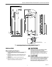
3. Install the mounting bracket (see Fig. 5). Mark the screw
holes for installing the mounting bracket on the damper
housing.
4. Remove the mounting bracket and actuator.
5. Drill or center punch the starting holes for the mounting
bracket screws (or use no.10 self-tapping sheet metal
screws).
6. Turn the damper blades to the desired normal position,
usually the closed position.
7. Place the actuator and mounting bracket back into
position over the damper shaft and install the mounting
bracket screws.
8. Tighten the shaft coupling set screw firmly by applying
7.5 lb-ft (10 N•m) of torque with a 13/32 in. (10mm)
wrench.
Fig. 5. Mounting bracket installation.
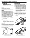
CAUTION
Using the actuator as a shaft bearing will damage
the device, reducing the functional life span.
In applications with side loads to the actuator shaft
coupling, a different coupling (such as the one
supplied with the foot mount kit)
must
be used.
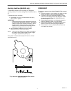
Wiring
CAUTION
Prevent electrical shock or equipment damage.
Disconnect all power supplies before wiring.
All wiring must comply with local electrical codes, ordinances
and regulations. The ML6195/ML6295 is designed for use
with a Class 2 power supply. Voltage and frequency of the
transformer used must correspond with the characteristics of
the motor and the power supply. See Fig. 6 and 7 for typical
wiring connections.
M12442