


Installing the Charger Installing Optional Meters
14
CHG-120 Instruction 11/22/04 PN: 52459:A FCI P/N:9000-0572
Installing Optional Meters
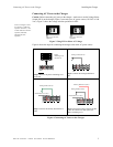
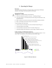
You can also order and install a ammeter (AM-1) or voltmeter (VM-1) for use with the
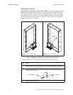
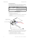
charger. If mounting an AM-1 or a VM-1, mount the meter to a BB-55 as shown in Figure
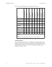
14. Table 6 contains descriptions and part numbers for these optional meters:
Installing an AM-1 To install an AM-1, follow these steps:
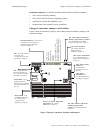
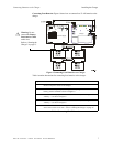
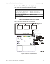
1. Cut jumper JP9 on the charger (Figure 13).
2. Connect the AM-1 harness to JP3 on the charger (Figure 11)—making sure to observe
proper polarity.
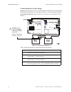
3. Mount the AM-1 into a mounting slot on the front of the BB-55 (Figure 14):
Figure 14 Mounting an AM-1 or VM-1 to a BB-55 Battery Box
Installing a VM-1 You can connect a VM-1 across a charger output circuit. For example,
to install a VM-1 to measure voltage from charger output circuit 1, follow these steps:
1. Connect the positive lead to TB2 Out 1 (+). See Figure 13.
2. Connect the negative lead to TB2 Out 1 (–). SeeFigure 13.
3. Mount the VM-1 into a mounting slot on the front of the BB-55 battery box.
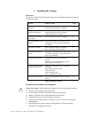
Item Part Number Description
Ammeter AM-1 0-10 A ammeter with a 3-ft. cable for connection to the
charger (JP3). Mounts into a BB-55 battery box only.
Voltmeter VM-1 0-50 V voltmeter with 3-ft. positive and negative leads
for connection to the charger output circuit. Mounts
into a BB-55 battery box only.
Table 6 Optional Meters
BB-55 Mounting Slot
AM-1 or VM-1
(BB-55 only)