


Installing the Charger Configuring the Charger
12
CHG-120 Instruction 11/22/04 PN: 52459:A FCI P/N:9000-0572
Configuring the Charger
You can configure the charger to do the following:
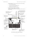
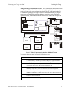
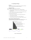
• Set the charger input power (see Figure 3 on page 5).
• Delay AC loss reporting (for Central Station applications); and
• Disable charger ground fault detection.
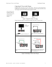
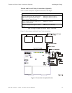
Figure 11 shows how to configure the charger for delaying the loss of AC reporting and for
disabling ground fault detection:
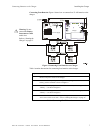
Figure 11 Configuring the Charger
Delay loss of AC Reporting If using a Digital Alarm Communicator (DACT), you must
delay the reporting of an AC loss condition to a central station. This delays activation of the
trouble bus and Form-C trouble contacts when AC fails. You can configure the charger for
an 8-hour or a 16-hour delay as follows:
• 8-hour delay – Cut and remove jumper JP8 on the charger (Figure 11).
• 16-hour delay – Cut jumper JP8; then, cut and remove resistor R100 (Figure 11).
Disable Ground Fault Detection To disable local (charger) earth fault detection, cut and
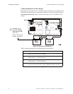
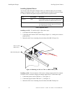
remove resistor R104 (Figure 11). Figure 12 contains a simplified block diagram that
shows ground fault detection disabled on a charger connected to multiple power supplies:
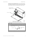
Figure 12 Disabling Ground Fault Detection
Delay loss of AC (16 hrs) cut and
remove R100, in addition to
cutting JP8
Disable ground fault detection
cut and remove R104
Delay loss of AC (8 hrs) cut JP8
On the charger,
disable ground fault
detection (cut R104).
Charger
Power
On Power Supply #2 and
#3, disable ground fault
detection.
# 1
On Power Supply #1,
enable ground fault
detection.
Supply
Power
# 2
Supply
Power
# 3
Supply