


Connecting the Charger to a Load Installing the Charger
CHG-120 Instruction 11/22/04 PN: 52459:A FCI P/N:9000-0572 11
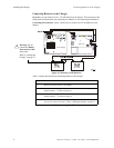
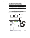
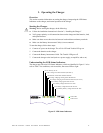
Adding the Charger for Additional Current Due to internal fuses, the maximum alarm
current that can be drawn from the batteries and passed through the charger’s two output
circuits is limited to 10 amps maximum (each circuit). The PS-12600 batteries, however,
are capable of supplying up to 45 amps of current in alarm. The remaining 25 amps of
alarm current can be drawn directly from the battery terminals to supply Notification
Appliance Circuits, control modules and other alarm devices as illustrated in Figure 10:
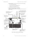
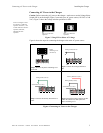
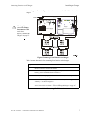
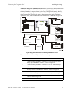
Figure 10 Typical Connections for Drawing Additional Current
To connect a charger as shown in Figure 10, follow these steps:
Step Action
1 Connect the Battery+ and Battery– terminals of the power supply to the charger
Battery output (TB2: Batt 1+ and Batt 1–) as shown in Figure 10.
2 Connect the Battery+ and Battery– terminals of the first AA-120 to the charger
output circuit (TB2: Out 2+ and Out 2–) as shown Figure 10.
3 Connect the Battery+ and Battery– terminals of the first Generic Audio Amp to
the charger output circuit (TB2: Out 1+ and Out 1–) as shown in Figure 10.
4 Connect the Battery+ and Battery– terminals of the second Generic Audio Amp to
the Battery+ and Battery– terminals of the first Audio Amp as shown in Figure 10.
5 Connect the Battery+ and Battery– terminals of the second AA-120 to the
batteries as shown in Figure 10.
6 Connect the batteries to the charger.
55 AH/60 AH
12 VDC
55 AH/60 AH
12 VDC
55 AH/60 AH
12 VDC
55 AH/60 AH
12 VDC
Power Supply
Charger
First
AA-120
Second
Generic
Audio Amp
First
Generic
Audio Amp
Second
AA-120