


Page 8SKU 94564 For technical questions, please call 1-800-444-3353.
Phase 2:
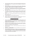
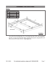
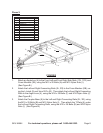
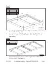
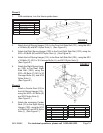
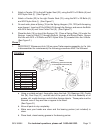
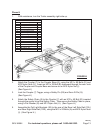
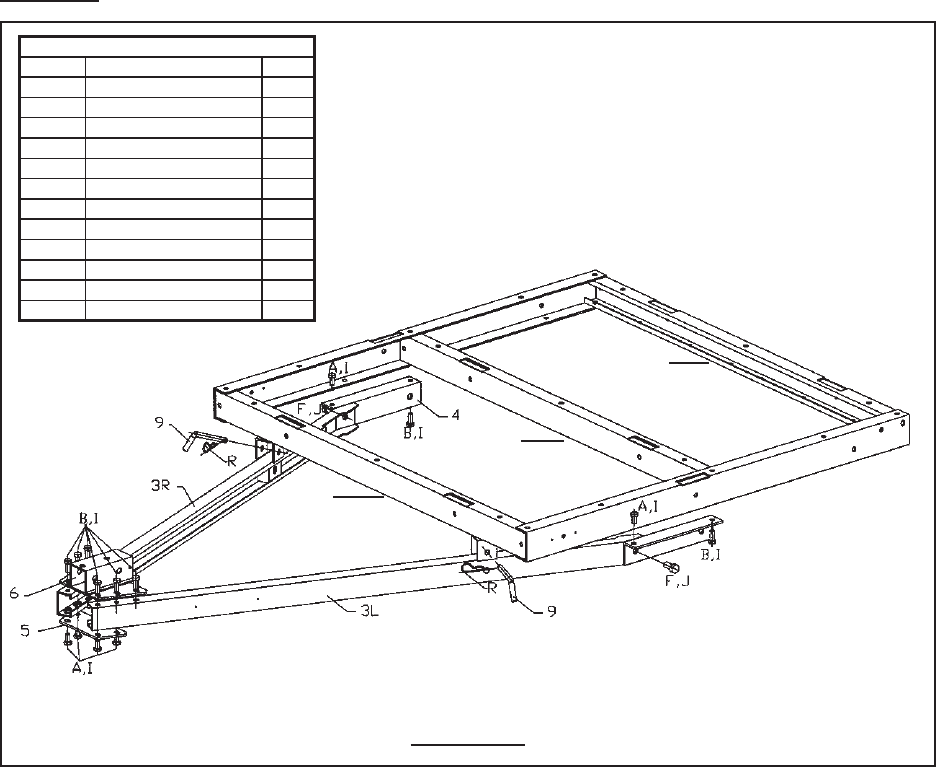
FIGURE B
2B
2B
2A
Parts Needed
Part # Description Qty.
3L Left Connecting Rail 1
3R Right Connecting Rail 1
4 Angle Iron 2
5 T-Plate 1
6 Coupler Base 1
9 L-Latch 2
A M10 x 20 Bolt 8
B M10 x 25 Bolt 6
F M14 x 30 Bolt 2
I M10 Nylon Nut 14
J M14 Nylon Nut 2
R 3mm R-Pin 2
Attach an Angle Iron (4) to the Front Left and Front Right Side Rails (1FL, 1FR) and
Cross Member (2B), using the M10 x 20 Bolts (A) and M10 Nylon Nuts (I).
(See Figure B.)
Attach the Left and Right Connecting Rails (3L, 3R) to the Cross Member (2B), us-
ing the L-Latch (9) and 3mm R-Pin (R). Then attach the Left and Right Connecting
Rails to the Angle Irons (4), using the M14 x 30 Bolts (F) and M14 Nylon Nuts (J).
(See Figure B.)
Attach the Coupler Base (6) to the Left and Right Connecting Rails (3L, 3R), using
the M10 x 25 Bolts (B) and M10 Nylon Nuts (I). Then attach the T-Plate (5) under
the Left and Right Connecting Rails, using the M10 x 25 Bolts (B) and M10 Nylon
Nuts (I). (See Figure B.)
1.
2.
3.