


SKU 45009, 92261 For technical questions, please call 1-800-444-3353 Page 6
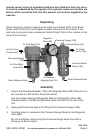
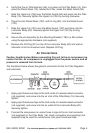
4. Connect the air output hose to the air outlet connector (not supplied) on the
Lubricator Body (6C). Quick connectors and couplings (not supplied) may be
used for convenience. Use pipe thread seal tape.
Operation
1. Turn on the Compressor and check for air leaks.
If any are found, turn the Compressor off, drain air from tank, and fix the
leak.
2. With the Compressor ON, turn the Air Pressure Adjusting Rod (1B) to adjust
the air pressure as read on the Pressure Gauge (12B).
3. Adjust the oil flow by viewing the View Dome (1C) and adjusting the Oil Feed
Adjustment Screw (4C) next to it.
4. Under pressure, press the Quick Release Button to expel any accumulated
moisture from the Air Filter. Do this daily.
Maintenance
1. Check oil level in Lubricator Plastic Bowl (10C) daily. Refill if below minimum
level.
2. Periodically disassemble the Air Filter and Lubricator assemblies and remove
all dirt and debris. Remove air pressure before cleaning.
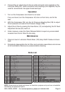
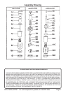
Parts List
Part Description
1A Filter Body
2A O-ring
3A Spiral Baffle
4A Filter Element
5A Umbrella Baffle
6A Screw Rod
7A Plastic Bowl
8A Plastic Drain
9A Metal Guard
10A Upper Lid
1B Adjusting Rod
2B Regulator Bowl
3B Spring Washer
4B Spring
5B Diaphragm
6B Regulator Valve
7B Regulator Valve
8B Spring
9B O-ring
Part Description
10B Pop-up Valve Cap
11B Mounting Bracket
12B Pressure Gauge
1C View Dome
2C Oil Plug
3C O-ring
4C Oil Feed Adjustment Screw
5C Drip Tube
6C Lubricator Body
7C Screw Rod
8C Coupler
9C O-ring
10C Plastic Bowl
11C Plastic Drain
12C Metal Guard
13C Upper Lid
1D Filter-Regulator Connector
2D Lubricator-Regulator Connector
NOTE: Some parts are listed and shown for illustration purposes only and are not available
individually as replacement parts.