


Page 7SKU 92174
For technical questions, please call 1-800-444-3353.
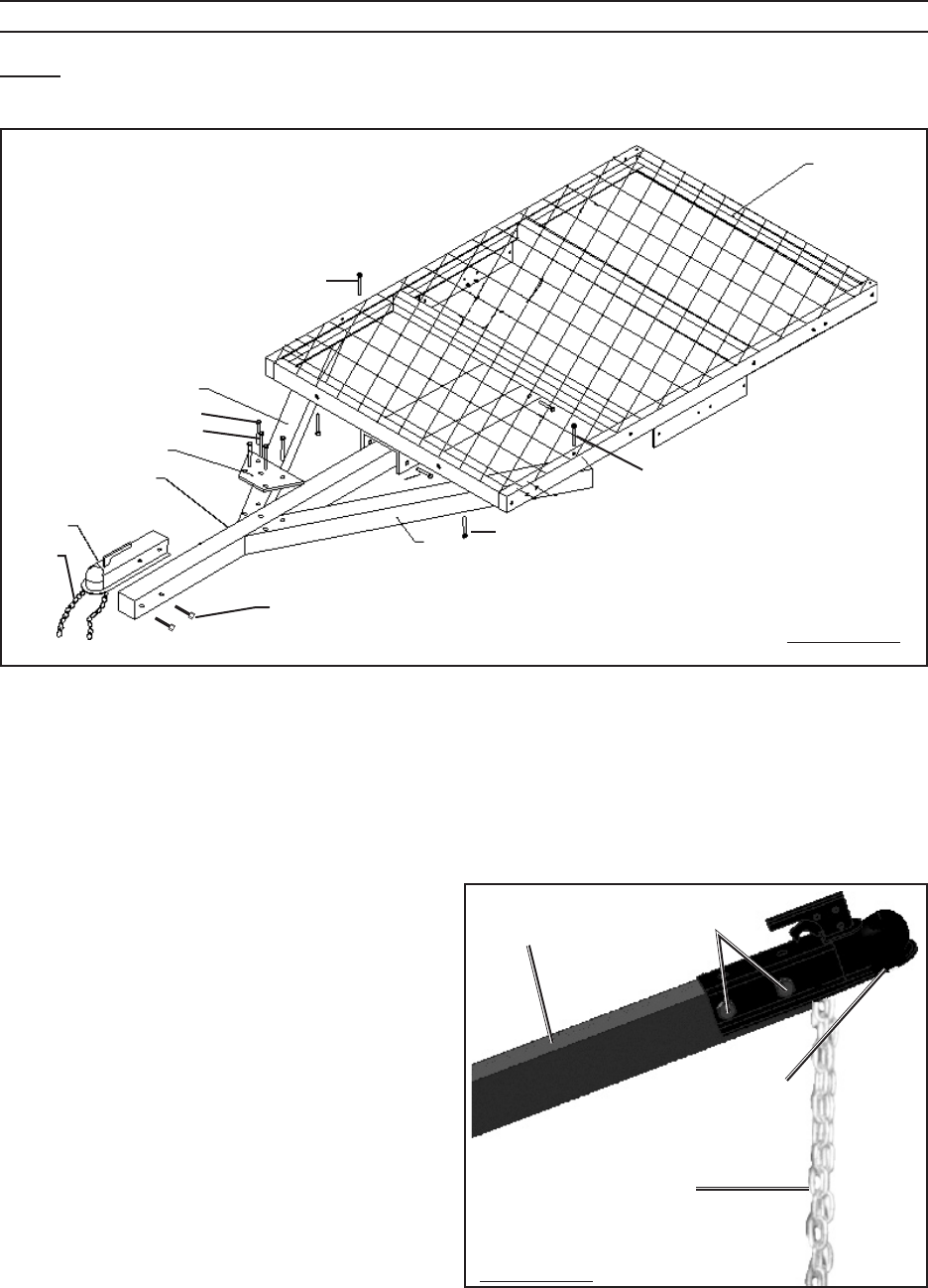
ASSEMBLY INSTRUCTIONS
Note: For additional references to the parts listed on the following pages, refer to the As-
sembly Diagram.
A2
8
A9
A13
2
2
1
2
2
A20
A20
A1
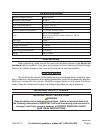
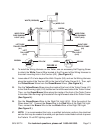
FIGURE A
2
A21
6
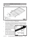
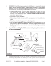
Attach the Tow Bar (A2) to the underside of the frame assembly, using two Bolts
(1), Lock Nuts (1), and Washers (1). (See Figure A.)
Attach the ends of two Side Rails (A20) to the front end of the Trailer Frame (A1),
using four Bolts (2), Lock Nuts (2), and Washers (2). Then attach the remaining two
ends of the Side Rails to the Tow Bar (A2), using the “T” Plate (A21), four Bolts (2),
Lock Nuts (2), and Washers (2). Secure the Center with one Bolt (6), Lock Nut (6),
and Washer (6). (See Figure A.)
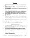
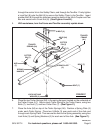
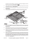
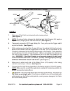
Slide the Hitch Coupler (A9) onto the
end of the Tow Bar (A2), and align
the two mounting holes of the Hitch
Coupler with the two side mounting
holes of the Tow Bar.
(See Figures A and B.)
Locate the center link in the Safety
Chain (A13), and place the center
link inside the end of the Tow Bar
(A2). Insert a Bolt (8) horizontally
through the side/forward mount-
ing hole of the Hitch Coupler (A9),
1.
2.
3.
4.
TOW BAR
(A2)
BOLT
(8)
SAFETY CHAIN
(A13)
FIGURE B
HITCH
COUPLER
(A9)
TOW BAR
(A2)
BOLT
(8)
SAFETY CHAIN
(A13)
FIGURE B
HITCH
COUPLER
(A9)
REV 05k, 06b, 07e