


Page 6SKU 66305 For technical questions, please call 1-800-444-3353.
attachment (21) into the sleeves
welded to the front end of the
platform and secure with a pull pin (7)
and a R-Pin (20) on either side.
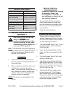
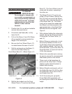
Support Leg and Wheel 4.
Assemblies: Identify the two support
leg/wheel assemblies. The front
assembly (74) has a threaded hole
between each pair of wheels. Insert
the front assembly through the
support arm tube at the lower, front
end of the scissor frame. Rotate the
assembly within the tube until the
hole in the centre aligns with the hole
in the tube. Secure with a bolt (26).
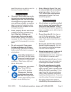
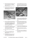
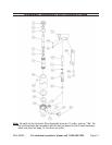
Now attach wheels (28), washers (29)
and retaining rings (30) in the order
shown in the diagram below. Identify
the two lock bolts (41) with hand
wheels attached and screw them into
the holes between the wheels on
either side. Insert the rear assembly
(27) through the support arm tube
at the lower, back end of the scissor
frame. Rotate the assembly within the
tube until the hole in the centre aligns
with the hole in the tube. Secure with
a bolt (26). Now attach wheels (28),
washers (29) and retaining rings (30).
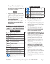
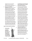
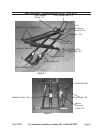
How to store the lift vertically.
The lift can be 1.
stored vertically
as shown in
gure below.
WARNING: In
this position the
lift is not free
standing and
must be secured
to a wall with a
heavy duty cable
or chain. Failure
to adequately secure the lift could
result in serious injury or death in
the event the lift tips over.
With the lift in its lowest position 2.
remove the ramp from the end of
the extended platform. Whilst the
platform is still extended remove the
pins from the ‘U’ shaped support on
the end of the extension and fold it
over. Use the two pins to lock it in
this position. Remove the two pins
from the other end of the extension
and push the extension back onto
the main platform until it lines up
with another pair of holes in the rails.
Insert the two pins through the rails to
lock the extension piece in position.
With the help of a second person, 3.
push the rear end of the Motorcycle
Lift against the wall where it will be
secured. Together lift the front end
into a vertical position. As it reaches
the vertical position the weight of the
lift will shift from the wheels to the ‘U’
shaped support leaving the wheels
slightly off the ground. Two people
should continue to support the lift
whilst it is manoeuvred up against the
wall. Whilst one person continues to
support the lift the other will secure
it in position with a heavy cable or
chains and a suitable lock.
Putting the lift back down for 4.
use. When returning the lift to the
horizontal position, equal care is
required to avoid injury to persons.
Reverse the lifting up steps. When
nally lowering the lift to the ground
take hold of the outer part of the
cable tie down bars at the chock
end of the lift to avoid ngers being
trapped under the wheel bars.