


Page 5SKU 66305 For technical questions, please call 1-800-444-3353.
Do not attempt to manually raise or 9.
lower the Lift. Operate the Lift hy-
draulically only as described in this
manual only.
Do not leave Lift unattended with a mo-10.
torcycle on it. The Lift is not for long term
storage.
Do not leave any load on the Lift for 11.
an extended period of time. This Lift is
not designed as a storage device. Re-
move motorcycle from Lift immediately
after completing service operation.
Use only on rm, level unobstructed 12.
surface able to support the weight
of the Lift, the vehicle, and any tools
that will be located in the work area.
Do not use Lift to move the motor-13.
cycle. This Lift is designed to lift the
motorcycle in place only.
Whenever a motorcycle is lifted, the 14.
Safety Bar (75) must be engaged
immediately before any further steps
are taken.
Do not use Lift for any aircraft purpose.15.
For indoor use only.16.
Do not ride on this Lift. Do not ride on 17.
the motorcycle as it is lifted. Riding
on Lift may cause personal injury.
Always control the speed of a loaded 18.
lift. It must raise or lower slowly
when loaded. Never attempt to lower
the Lift when loaded by using the
yellow No Load Pedal (71). The No
Load Pedal is only used to lower the
Lift when it is not loaded.
Do not lower the motorcycle quickly. 19.
Only use the Load Pedal (69) to
slowly lower the Lift when there is a
motorcycle on it. NEVER allow the
vehicle to drop suddenly.
The warnings and precautions dis-20.
cussed in this manual cannot cover
all possible conditions and situations
that may occur. It must be under-
stood by the operator that common
sense and caution are factors which
cannot be built into this product, but
must be supplied by the operator.
Failure to comply with these warn-
ings may result in injury or damage to
property.
SAVE THESE
INSTRUCTIONS.
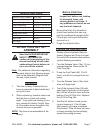
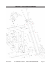
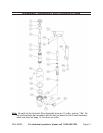
The Lift comes completely assembled,
except for the following items: (Refer to
the exploded drawing).
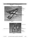
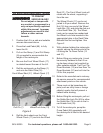
Tie Down Rings: 1. The two front tie
downs are longer than the rear pair.
Slide the front tie downs (13) onto the
rods welded at either side of the front
end of the platform, and secure them
with bolts (14) and nuts (15). Attach
the shorter rear tie-downs (31) to the
rear rods and secure with bolts (14)
and nuts (15).
Wheel Chock: 2. Place the wheel
chock (17) on to the front end of the
platform and align it with a suitable
pair of holes. Slide the long bolt (19)
through a hole in the side of the
platform and through the sleeves
welded to the back of the chock and
out the other side of the platform.
Secure with nut (18).
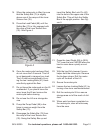
Front Wheel Attachment. 3. Drop the
ends of the ‘U’ shaped front wheel
ASSEMBLY INSTRUCTIONS