


Page 4SKU 47845 For technical questions, please call 1-800-444-3353.
Assembly
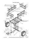
Refer to the Assembly Drawing on page 7.
1. Attach the four Support Panels (A2) to the Axle (A6) using four Bolts (B1) and Lock
Nuts (B2). Set aside.
2. Attach the Connect Bar (A5) to the Tow Bar (A4) with two Bolts (B5) and two Lock
Nuts (B6).
3. Attach the Support Bracket (A3) to the Tow Bar (A4) with L Pin (B7) and secure it
with cotter R Pin (B8).
4. Connect the other end (the end without the Connect Bar (A5) of the Tow Bar (A4) to
the center of the Axle (A6) using Bolt (B4) and Lock Nut (B2).
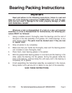
5. WHEEL BEARINGS AND WHEEL ASSEMBLY
A. The wheel bearings are shipped dry and MUST be packed with bearing grease prior to
assembly. Wear latex gloves and apply grease liberally around the bearing rollers.
B. Wipe the two bearing races on each wheel clean. It is also recommended that the
inside of the where the dust cap will go be wiped with some grease. This will remove
surface rust and make the installation of the caps easier.
C. Insert the bearings into one wheel, matching the taper of the rollers to that of the races.
Hold the bearings in place, while sliding the hub over the axle. Slide one large Washer
(A8) over the spindle, then install and hand-tighten one Castle Nut (A9) to retain the
wheel. Repeat with the other wheel.
D. Tighten the Castle Nut firmly, but not excessively. A 31mm socket wrench is best for
this. Now back the nut off so that the nearest slot in the shoulder aligns with the cotter
pin hole in the spindle. Test the wheel for free rotation. If necessary, loosen the nut
another slot (1/6 of a turn), and check again. The wheel should rotate freely, yet have
minimal side play on the spindle.
E. Insert the Cotter Pin (A10) through the slot and the spindle hole, then bend the longer
leg up with small pliers. Repeat steps D and E on the opposite side.
F. The dust caps are intended to protect the bearing. They fit tightly and require some
patience to install. Tap them in with a mallet.
6. Set the Frame (A1) so that the holes in the center of the bracket crossing the middle
of the bed line up with the four holes on the top of the two Support Panels (A2). Make
sure the Frame (A1) is positioned with the two holes facing front (see Assembly
Drawing on page 7). Loosely attach them with four Bolts (B1) and four Lock Nuts
(B2).
7. Attach the top of the Support Bracket (A3) to the two holes on the front of the Frame
(A1) with two Bolts (B3) and Lock Nuts (B2). Go back and tighten the hardware used
in step 6 above.
8. If using wooden stake side panels (not included), slide the two side panels into the
Bed Frame Sockets (see Assembly Drawing on page 7). Repeat with two front/rear
panels. Make sure the vertical supports that fit into the sockets face the outside of the
Trailer. Secure each side panel into the Bed Frame Sockets by inserting a screws
(screws included in Wooden Stake Panel Kit).
REV 05/03; 12/03; 05/05